HuxleyXAxis
General
This page and its peers should guide you through assembling a RepRap Huxley from the TechZone kit, or from parts you have printed which are the same as the TechZone parts. It is a work in progress, and needs some help, feel free to edit this document to add comments of you your own, or contact us [here] and send us messages asking us for better clarification or details.
I am starting by posting the pictures I have, and over the next few days, I will fill in the instructions and detials (24 Dec 2010)
Thanks,
Lambert (TechZone R&D/Support/Documenter)
You can access this page and it's peers (for the other parts of the Huxley assembly from the Main Huxley page or from the TechZone Huxley Page
Contents
Whene assembling the X Axis, assemble the parts just finger tight, and into aproximate areas. When it is all together, we will fix things by measurements, and tighten them up.
X Carriage
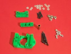
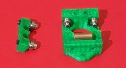
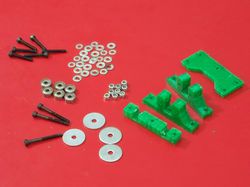
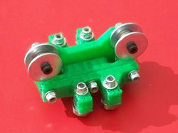
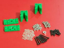
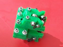
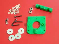
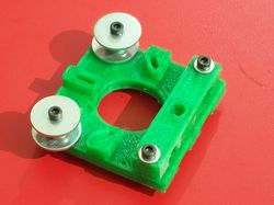
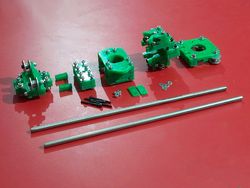
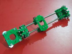
On the left is a picture of the parts used to make the X axis carriage (some people call it a shuttle) It is shown assembled on the right:- (1) X Carriage - from the printed parts set
- (1) 180 side of the X Carriage - from the printed parts set
- (1) 360 side of the X Carriage/Bushing Clamp - from the printed parts set
- (1) Graphite filled Bronze bushing
- (6) 3mmX30mm bolts
- (4) 3mmX20mm bolts
- (16) 3mm washers
- (10) 3mm nyloc nuts
- (4) 623zz bearings
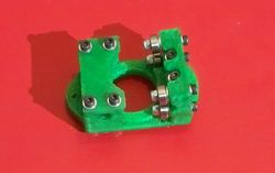
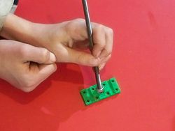
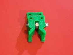
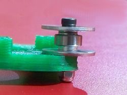
The Image here shows the 180 Degree bearing piece already installed to the Carriage, use (2) 30mm bolts with nuts and washer to do this, the head of the bolt goes to the bottom and the nut goes on top of the carriage (top of the carriage is the smooth side). These two bolts should allow you to adjust the tension with which the bearings ride on the smooth bar, but it is easiest to make this adjustment after the axis is all assembled, so leave them fairly loose for now.
There is an added bennefit of doing this in this way, as the bronze wears slightly, it lays graphite down on the stainless steel rod. You will want to make sure to use the same rod in your final assembly (I usually just set it aside the way it is and don't take the rod out of the bushing again.
I also recommend that you add a drop or two of your favorite machine oil, like sewing machine oil, or bicycle chain oil to the shaft, after you have seated the bushing.
Z180 Degree and X Axis Idler
Z Nut Retainers
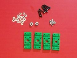
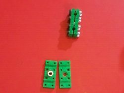
The following parts are used to assemble and prepare the Z Nut Retainers Assembled version is shown on the right.
- (4) Z Nut Retainers
- (8) 3mm X 20mm bolts
- (16) 3mm washers
- (8) 3mm nyloc nuts
- (2) 6mm nuts
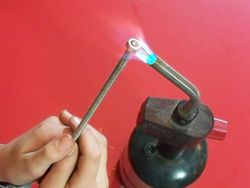
The first thing we need to do is to make sure that the 6mm nut will fit into the space provided for it. It is usually tight and need to be carved out larger, you can do this with a knife, but I have found that it is easier to heat a nut up and then press it into the space as shown on the right. I use a standard plumbing torch to heat the nut on the end of a piece of the threaded Rod. Don't get the nut too hot, it only need to be about 130 degrees celcius to do this well.
You could also use a soldering iron, hot plate, or oven to heat the nut. Or, as stated earlier, you can use a knife to carve the space to fit.
I press the nut it while it is warm - as shown on the right, once it is in about half way (a little less really) I take it back out and perform the same operation on the other three Printed Nut Retainers.
Once they are all prepared you use the eight 20mm bolts and put two of them together with one of the nuts in between. Don't tighten it down yet, we want to be able to slip the smooth bar into the spaces there, without very much effort.
Z360 Degree portion
On the left is a photo of the parts used to build the Z 360 portion of the X Carriage, an assembled shot is on the right. The parts used in this are:- (2) Z 360 - printed parts
- (2) Z Nut Retainers - printed parts -Make sure you have prepared them for use with the steps above
- (6) 623zz ball bearings
- (8) 3mmX20mm bolts
- (8) 3mmX30mm bolts
- (16) 3mm Nyloc nuts
- (30) 3mm washers
- (1) 6mm nut
Do this to both of the Z 360 printed parts.
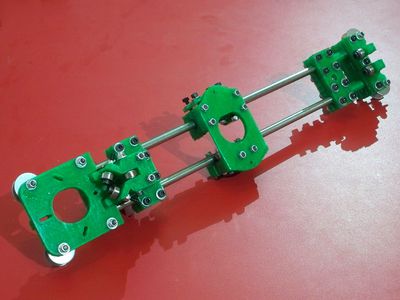
Finally, bolt the two parts together, using two 30mm bolts, and 4 20mm bolts. The finished product should look like the unit in the photo above right. Don't tighten these bolts yet, we need to slide smooth bar into them in a few minutes. (leave them REALLY loose).
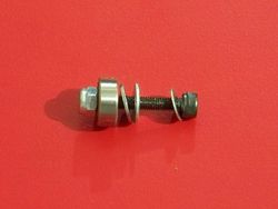
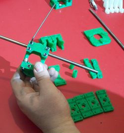
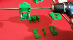
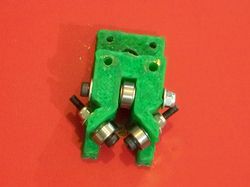
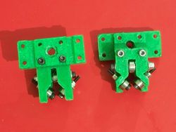
Below are a few extra photos I had, which may help make the assembly more clear - or not...
X Axis Motor Mount
Put them together
