HuxleyXAxis

General
This page and its peers should guide you through assembling a RepRap Huxley from the TechZone kit, or from parts you have printed which are the same as the TechZone parts. It is a work in progress, and needs some help, feel free to edit this document to add comments of you your own, or contact us [here] and send us messages asking us for better clarification or details.
I am starting by posting the pictures I have, and over the next few days, I will fill in the instructions and detials (24 Dec 2010)
Thanks,
Lambert (TechZone R&D/Support/Documenter)
You can access this page and it's peers (for the other parts of the Huxley assembly from the Main Huxley page or from the TechZone Huxley Page
Contents
Whene assembling the X Axis, assemble the parts just finger tight, and into aproximate areas. When it is all together, we will fix things by measurements, and tighten them up.
X Carriage


- (1) X Carriage - from the printed parts set
- (1) 180 side of the X Carriage - from the printed parts set
- (1) 360 side of the X Carriage/Bushing Clamp - from the printed parts set
- (1) Graphite filled Bronze bushing
- (6) 3mmX30mm bolts
- (4) 3mmX20mm bolts
- (16) 3mm washers
- (10) 3mm nyloc nuts
- (4) 623zz bearings


--AlexRa: The bronze bushing tends to lock the X axis, resulting in jerky movements and missing steps. I ended up cutting the bushing in two part and put them into the groove as far away from each other as possible, at the edges of the X-carriage. This gave much smoother movements and better yaw-axis stability of the X carriage (sorry, the image is Photoshopped, that was easier than to take apart the real thing (again)):


The Image here shows the 180 Degree bearing piece already installed to the Carriage, use (2) 30mm bolts with nuts and washer to do this, the head of the bolt goes to the bottom and the nut goes on top of the carriage (top of the carriage is the smooth side). These two bolts should allow you to adjust the tension with which the bearings ride on the smooth bar, but it is easiest to make this adjustment after the axis is all assembled, so leave them fairly loose for now.

There is an added bennefit of doing this in this way, as the bronze wears slightly, it lays graphite down on the stainless steel rod. You will want to make sure to use the same rod in your final assembly (I usually just set it aside the way it is and don't take the rod out of the bushing again.
I also recommend that you add a drop or two of your favorite machine oil, like sewing machine oil, or bicycle chain oil to the shaft, after you have seated the bushing.

Z180 Degree and X Axis Idler


- (2) Z 180 - printed parts
- (1) X Axis Bar Clamp, Idler end (does not have a recess for bolt head - the motor end has a recess for bolt head)
- (1) X Axis Idler - Printed Part
- (3) 3mm X 30mm bolts
- (6) 3mm X 20mm bolts
- (4) 3mm fender washers
- (9) 3mm nyloc nuts
- (29) 3mm washers (give or take a few)
- (6) 623 bearings


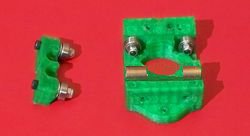
To assemble them, place the X Axis smooth bar clamp onto the same side of the Idler as where the belt idler bearings are sitting. This clamp is not symetrical and will fit differently if turned aroud 180 degrees. I cannot tell that it makes any structural difference which way you put it, but in one directions it seems to fit in a more asthetic manner. Then place one of the Z 180 parts on each side and use the three 3mm X 30mm bolts to hold them together. Do not tighten them yet, you will need space to fit the smooth bars under the clamp.
Your assembly should now look like the photo at the top right of this section.
Z Nut Retainers


The following parts are used to assemble and prepare the Z Nut Retainers Assembled version is shown on the right.
- (4) Z Nut Retainers
- (8) 3mm X 20mm bolts
- (16) 3mm washers
- (8) 3mm nyloc nuts
- (2) 6mm nuts

The first thing we need to do is to make sure that the 6mm nut will fit into the space provided for it. It is usually tight and need to be carved out larger, you can do this with a knife, but I have found that it is easier to heat a nut up and then press it into the space as shown on the right. I use a standard plumbing torch to heat the nut on the end of a piece of the threaded Rod. Don't get the nut too hot, it only need to be about 130 degrees celcius to do this well.
You could also use a soldering iron, hot plate, or oven to heat the nut. Or, as stated earlier, you can use a knife to carve the space to fit.

I press the nut it while it is warm - as shown on the right, once it is in about half way (a little less really) I take it back out and perform the same operation on the other three Printed Nut Retainers.
Once they are all prepared you use the eight 20mm bolts and put two of them together with one of the nuts in between. Don't tighten it down yet, we want to be able to slip the smooth bar into the spaces there, without very much effort.
Note even when these are installed on the smooth bars and tightened down, there should be a small gap between the two halves.
Z360 Degree portion


- (2) Z 360 - printed parts
- (2) Z Nut Retainers - printed parts -Make sure you have prepared them for use with the steps above
- (6) 623zz ball bearings
- (8) 3mmX20mm bolts
- (8) 3mmX30mm bolts
- (16) 3mm Nyloc nuts
- (30) 3mm washers
- (1) 6mm nut

Do this to both of the Z 360 printed parts.


Finally, bolt the two parts together, using two 30mm bolts, and 4 20mm bolts. The finished product should look like the unit in the photo above right. Don't tighten these bolts yet, we need to slide smooth bar into them in a few minutes. (leave them REALLY loose).
Below are a few extra photos I had, which may help make the assembly more clear - or not...


X Axis Motor Mount


Parts used to assemble this are:
- (1) X Axis Motor Mount - printed parts
- (1) X Axis Bar Clamp, motor end - printed parts
- (4) MudGuard/Fender washers
- (2) 623zz bearings
- (4) 3mmX20mm bolts
- (4) 3mm nyloc nuts
- (18) 3mm washers
--NOTE-- the bar clamp looks very similar to the idler end bar clamp, but, the motor end has a recess in it for a bolt head, so that the bolt will reach far enough in to connect to the motor when we mount the motor.

I needed two washers on one side and three washers on the other side of the bearing, in order for the belt to fit correctly. You may need a different number of washers than I needed. The way to test it is to make your stack, and then see how your belt fits. The belt should fit, with just a little extra room.
Put them together

The list of parts used is:
- (1) X Axis Motor Mount - assembled above
- (1) X Axis Z 360 portion - assembled above
- (1) X Carriage - assembled above
- (1) Z Nut Retainer set - assembled above
- (1) X Axis Idler assembly - assembled above
- (2) X Bar Spacers - printed parts
- (2) X Axis Belt Clamps - printed parts
- (4) 3mmX30mm bolts
- (4) 3mm nyloc nuts
- (4) 3mm washers
- (2) X Axis Smooth bars - these are the longest smooth bars in the set, aprx 295mm (11-5/8") long


Squaring, and truing the size/shape
The squaring and truing of this axis is fairly simple. We want to make sure that the X Carriage 180 side has good contact between the bearings and the smooth bar. We want to make sure that the Z smooth bar will fit and ride in the 360 and the 180 sides without too much tension.
The X Carriage 180 is adjusted by means of the two bolts that hold the bottom bearing portion onto the main carriage. Simply loosen or tighten them as needed. There should be just enough tension for the bearings to make contact with the bar.
The Z 180 side is the easiest of the three, we don't check to make sure there is enough tension at this time, but we want to make sure ther is not TOO MUCH tension. The bar should fit between the bearings on the 180 end and should not rub on the plastic parts when it is "nearly" centered in the bearings.
The Z 360 side is the most temperamental. I often have to trim the shoulder between the straight bearing and the angled bearings. I trim it with a knife. The amount I have had to trim is very small when I have everything else adjusted well. The bar should go down through both sets of bearings and not rub on anything. If it is rubbing, I would first check to see that the parts are all fitting together as they should and the two 360 bearing clamps are parallel to each other. A common mistake here is to have the nut end of the bolts holding the 360 bearing and the Z nut retainer turned towards each other, rather than the heads of the bolts (take a close look at the pictures above, the nuts are on the outsides of the assembly, not the inside).
I have not posted pictures with this explainations, since I am not sure what to take pictures of to better describe the adjustments (other than the pictures in the steps above). If you have some please add them to this gallery... or send them to me and I will add them (see how to contact me above, I will send you my email address).