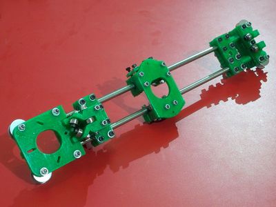
HuxleyXAxis
General
This page and its peers should guide you through assembling a RepRap Huxley from the TechZone kit, or from parts you have printed which are the same as the TechZone parts. It is a work in progress, and needs some help, feel free to edit this document to add comments of you your own, or contact us [here] and send us messages asking us for better clarification or details.
I am starting by posting the pictures I have, and over the next few days, I will fill in the instructions and detials (24 Dec 2010)
Thanks,
Lambert (TechZone R&D/Support/Documenter)
You can access this page and it's peers (for the other parts of the Huxley assembly from the Main Huxley page or from the TechZone Huxley Page
Contents
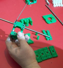
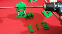
Whene assembling the X Axis, assemble the parts just finger tight, and into aproximate areas. When it is all together, we will fix things by measurements, and tighten them up.
X Carriage
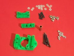
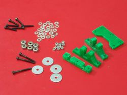
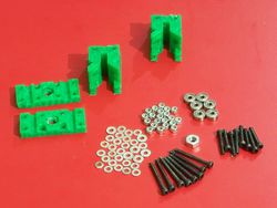
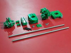
On the left is a picture of the parts used to make the top unit:- (1) X Carriage - from the printed parts set
- (1) 180 side of the X Carriage - from the printed parts set
- (1) 360 side of the X Carriage/Bushing Clamp - from the printed parts set
- (1) Graphite filled Bronze bushing
- (6) 3mmX30mm bolts
- (4) 3mmX20mm bolts
- (16) 3mm washers
- (10) 3mm nyloc nuts
- (4) 623zz bearings
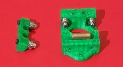
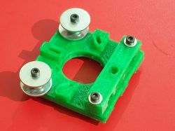
Z180 Degree and X Axis Idler
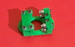
Z360 Degree portion
X Axis Motor Mount
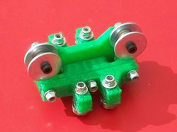
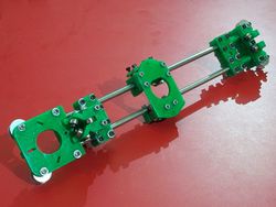
Put them together
