Generation 3 Electronics/Tech Zone Remix/Installation
Overview =
This page will attempt to provide information on how to connect all the electroncis together, and make sure they are talking.
Contents
General information
Making the Cables (I know, they are a pain...)
Hooking up the Main board
Hooking up a Stepper Controller
Connecting the Extruder Controller
There are several wires that hook into the extruder controller. The photos and descriptions below have most of the wires not featured in that photo remove, for clarity.
Connecting the Main board to the Extruder Controller
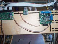
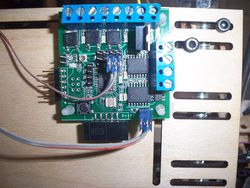
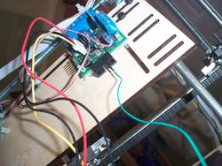
The main board is connected to the Extruder board with two separate wires. The first wire (shown as the bottom wire in the photo) is the RS485 communications wire, the main board communicates over this wire to the extruder, to give it commands, and to receive information back (like the temperature of the Hot End). The second wire is only needed if you are using a stepper motor with your extruder. It uses the I2C communications port off of the main board and the D9/D10 pins on the extruder Controller. This cable carries the step and direction information for the extruder's stepper motor.A little background: These two boards are connected together with 2 wires, in most of the modern implementations of the RepRap, but the original design only used the RS485, and expected you to use a variable speed DC motor. When the extruder evolved to use stepper motors, someone figured out how to make all of that work (with timings, PWM and other technical stuff I am not going into on this page), but it requires the second connection to pass the working information to the extruder, this is required, because the RS485 communications protocols are not "Fast" enough to deal with the information needed for the stepper motor
The photo on the right is just a close up of the same wires.
Connecting in the TechZone Thermocouple A/D converter
This converter is in a pre-release format, and is a variation of the adapter found on the Thermocouple_Sensor_1_0 page, but we have changed the firmware so that you do not need to remove the capacitor as shown in the instructions under that link. (Read that page for background, history, inspiration, whatever, but follow these directions if you received your A/D converter from TechZoneCommunications)
For information on the Firmware, and to download the firmware file, see TechZone_Thermocouple_Firmware page.(coming soon)
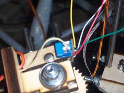
The four pin connector is connected to the four pins on the mainboard as shown in the photo on the left and the single wire is connected into one of the ten pins in the old quadrature connector as shown on the right.
Before turning on the heater, you need to make sure the thermocouple is connected with the correct polarity. To do this, load the RepRap host software and go to the extruder tab. It should be providing you with a temperature reading. If you put your finger on the tip of the extruder for a minute, you should see that temperature go up. If it goes down, then you have the polarity of the thermocouple reversed and you need to swap the wires.
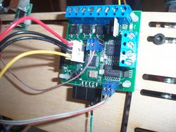
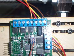
The Photo on the right of this text, shows the connection of the heater lead wires to the Extruder Controller. it is the second set of wires from the right side of the 8 terminal block. This picture shows them as red and orange wires. They are not polarized (you can switch them places and it won't matter). I recommend not hooking these two wires up until you are ready to heat up your extruder tip. That should happen after you test all other aspects of your extruder and know that it works.
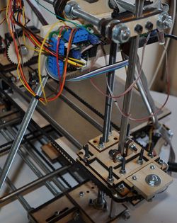
Here are some more photos to help with the details (a picture is better than any words I can create)
