Generation 3 Electronics/Tech Zone Remix/Instalacion en Espanol
Overview
esta pajina esta siendo creada. esperala procsima mente!
To see this page in English, click here: Generation_3_Electronics/Tech_Zone_Remix/Installation
Contents
- 1 Overview
- 2 asiendo los cables (yo se que , son un dolor de cabesa...)
- 3 conectando el modulo maestro (Min board)
- 4 conectando el controlador de motores(Stepper Controller)
- 5 Conectando el controlador de (bamos a llamarle) "Extruder", (Extruder Controller)
- 6 A few different ways to connect Temperature sensors
- 7 Connecting a Stepper Controller to Drive the Extruder Stepper Motor
informacion General
las siguientes instrucciones son proveidas y aplican para las conecciones de electronicas
vendidas por TechZoneCommunications. para codigos y mas informacion sobre estos electronicos ver seta pajina:Generation_3_Electronics/Tech_Zone_Remix
asiendo los cables (yo se que , son un dolor de cabesa...)
la malloria de problemas que los usuarios tinen, al ensablar y conectar los electronicos, son relasonadas con la forma de ensamblar los cables mismos. es importante asegurarse que los cables estan hechos correctamente , y asegurarse que tienen buen contacto.
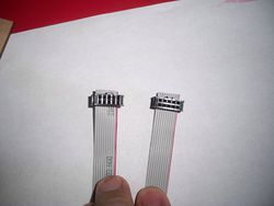
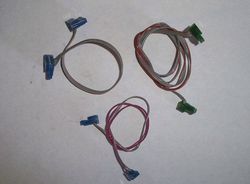
coneccion de diez cables con conetores negros de IDC
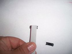
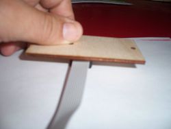
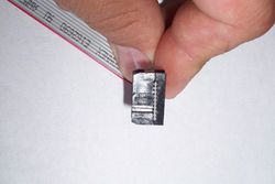
el cable de diez contactos . poner el cable sobre los contactos (foto de ariba derecha) despues colocar la"tapa" sobre ellos. usando un pedso de madera para aplicar presion de manera igual (como en la segunda foto en la derecha), presion desigual puede rresultar en danos ala tapa o falso contacto en el cable.
se debe poner atension especial en poner la orilla roja en la misma direccion en las dos orillas (mirar de serca en la foto isquierda arriba ), conectarlos incorrectamente no funsionaran como deben.
cables de dos, tres, y seis lineas
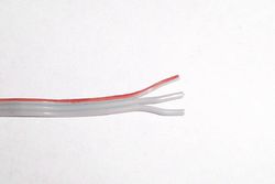
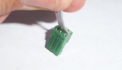
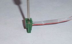
estos alambres pueden tener conector blanco, azul o verde , trbajan de la misma forma apesar de el color. y son ensablados de la misma forma. algunas personas prefieren usar conectores de sus computadoras viejas u otro electronico, enves de aser estos cables. y tambien esta bien...los cables se necesitan rromper y separar en el final, para que entren el los espasios de este conector. despues se pone el final de el cable dentro de el espacio de el conector pasando IDC contactos en el conector. se pueden precionar los cables en los contactos IDC usando un desarmador pequeno o otra cosa, yo he tenido buena suerte usando en pedaso de lamina, con una orilla doblada donde presiono, esto es para no cortarme al presionar los cables. attension: (usar un desarmador muy grande doblara los contactos y estos no cortaran la insulasion de el cable resultando en un falso contacto), otra solocion es cortar un espacio en la punta de un desarmador plano, para poder precionar el cable en cada lado de el contacto
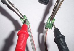
al terminar de ensamblar los cables, deben ser probados con un voltimetro, para asegurarse que ay una buena coneccion
las fotos muestran como aser un cable de tres conectores, pero todos los cables de tres o mas conectores se asen de la misma forma.
conectando el modulo maestro (Min board)
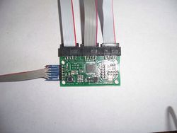
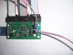
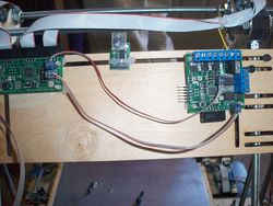
estas dos fotos muestran el modulo maestro conectado. la foto en la isquierda no tiene los dos, cables de dos alambres conectados, solo para que se mire mas claramente los demas cables
El USB a TTL adaptador conectado a el modulo maestro con un cable de seis lineas. el cable de seis lineas se conecta en la isquierda de el modulo, con la "linea marcada" en la parte de arriba (opuesto a alo que el modulo controlador de motores ). el modulo obtiene luz de el USB port, y este prende cuando el cable esta conectado.
El X, Y, y Z conectores en la parte de arriba de el modulo maestro con cables de diez lineas. cada cable biene de su respectibo controlador de motor.
Los dos cnectores de dos cables ambos ban conectados a el controlador del extruder, el de arriba es el SDA/SCL lineas y lleba el paso y direccion informacion para el extruder's motor de pasos. el cable de abajo es RS485 y se puede conectar a cualquiera de las cutro conecciones de el modolo maestro. la forma de conectarlo esta en la foto. se puede conectar asta 4 extruders a este modulo maestro.
conectando el controlador de motores(Stepper Controller)
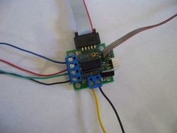
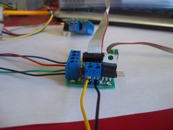
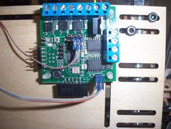
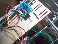
arriba en la derecha, es una foto de controlador de motores, con todos los cables conectados.
los conectores de diez lineas conectados a el lugar correcto en el modulo maestro(X, Y, or Z) al aser el cable, asegurarse que las dos orillas de color esten para el mismo lado, poner el lado de color diferente, tu cable se mirara al reverso que la foto. esto esta bien si las dos orrillas estan de la misma forma
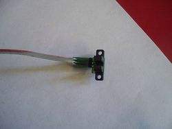
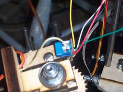
cable de tres lineas ba conectado a el optico final y parar, en esta foto, esta conectado a el maestro los otros tres pins son para max final y parar, si tu quieres conectar uno. para quienes que estan acostumbrados a mirar en el modulo para igualar la polaridad de el cable, olviden esta parte, (por error) algunos fueron marcados incorrecta mente, aqui esta como poner el lado rojo en las dos orillas de el cable: en el controlador de motor, el cable rojo ba asia el regulador de luz (es la cosa negra con la parte de atras plateada que esta a un lado de la coneccion de la luz) en el sensor optico, ba ala orrilla contraria de la luz (led) la luz de (led) es la cosita blanca en la parte de abajo lado isquierdo de el sensor optico en la foto. la tersera foto en la derecha es el sensor optico con el cable conectado, (presionarla para aserla mas grande) y obserbar lo rojo en el cable mas clara mente
la foto de arriba derecha muestra los cables de la luz. El cable amarillo en esta foto es 12v+ y el cable negro 12v-
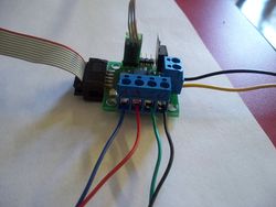
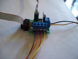
La segunda foto abajo en ambos isquierda y derecha muestra la conneccion de los cables para los motores. la foto en la isquierda muestra el azul, rojo, verde, y negro y la foto en la derecha solo son cables de difernte color. si el motor ba en direccion opuesta a la deseada, debe boltear los cables 180 grados, por ejemplo cambiando el azul con el negro y cambiando el rojo por el verde.
mas informacion se puede encontrar aqui Stepper_wiring esto talbes pudiera ayudar a conectar diferentes motores de este tipo.
Conectando el controlador de (bamos a llamarle) "Extruder", (Extruder Controller)
varios cables se conectan a el controlador de extruder. las fotos y descripciones en seguida muestran como aserlo. todos los cables nesecitan estar conectados, para que el Extruder trabaje correcta mente.
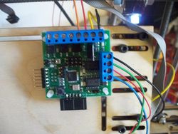
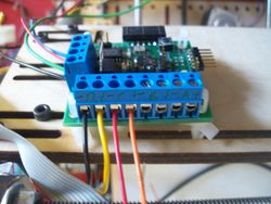
Conecccion completa de el Controlador de Extruder
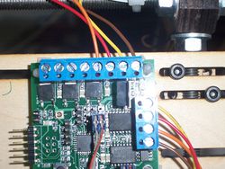
las conecciones con tornillos estan marcadas, y mas o menos explicadas, pero yo se que con fotos se puede entender como aser estas concciones mucho mejor (que siguiendo las marcas de las terminales con tornillo).
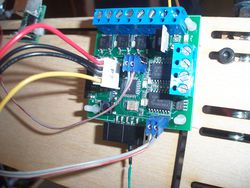
la foto de arriba el la isquierda muestra todos los cables conectados a las terminales con tornillo (todos los demas cables no estan conectados). en la derecha los cables de la luz estan conectados, tambien los cables de el calentador en la punta de el extruder. los cables de la luz estan polarizados y 12v + debe ser conectado a la segunda posicion (amarillo en esta foto) y 12v- (o tierra) debe ser conectado a primera posicion (negro en esta foto).The heater leads are red and orange in this photo, but it does not matter the color, or order of these wires. They are connected to the C position on the terminal blocks.
A and B positions on these terminal blocks can be programmed for other loads, such as a cooling fan, or a heated bed.
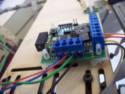
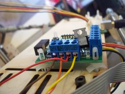
The second photo on the left is of the motor wires. I have used the most common color of wires, but your may be different. If the motor direction is reversed from what you expect, then simply flip all the wires 180 degrees, by swapping blue with black, and red with green.
The second photo on the right is just like the photo on the left, but with a different colored set of wires
More information about stepper motor wiring can be found at Stepper_wiring
Connecting the Main board to the Extruder Controller
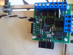
The main board is connected to the Extruder board with two separate wires. The first wire (shown as the bottom wire in the photo) is the RS485 communications wire, the main board communicates over this wire to the extruder, to give it commands, and to receive information back (like the temperature of the Hot End). The second wire is only needed if you are using a stepper motor with your extruder. It uses the I2C communications port off of the main board and the D9/D10 pins on the extruder Controller. This cable carries the step and direction information for the extruder's stepper motor.A little background: These two boards are connected together with 2 wires, in most of the modern implementations of the RepRap, but the original design only used the RS485, and expected you to use a variable speed DC motor. When the extruder evolved to use stepper motors, someone figured out how to make all of that work (with timings, PWM and other technical stuff I am not going into on this page), but it requires the second connection to pass the working information to the extruder, this is required, because the RS485 communications protocols are not "Fast" enough to deal with the information needed for the stepper motor
The photo on the right is just a close up of the same wires.
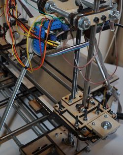
Also of interest in this photo, he made a belt tensioner for the X axis, you can see it near the bottom right of the photo.
A few different ways to connect Temperature sensors
There are several ways to detect the temperature of the hot end of the extruder, below we have shown a couple of them. Use the one that fits your configuration
Connecting in the TechZone Thermocouple A/D converter
This converter is in a pre-release format, and is a variation of the adapter found on the Thermocouple_Sensor_1_0 page, but we have changed the firmware so that you do not need to remove the capacitor as shown in the instructions under that link. (Read that page for background, history, inspiration, whatever, but follow these directions if you received your A/D converter from TechZoneCommunications)
For information on the Firmware, and to download the firmware file, see TechZone_Thermocouple_Firmware page.(coming soon)
The four pin connector is connected to the four pins on the mainboard as shown in the photo on the left and the single wire is connected into one of the ten pins in the old quadrature connector as shown on the right.
Before turning on the heater, you need to make sure the thermocouple is connected with the correct polarity. To do this, load the RepRap host software and go to the extruder tab. It should be providing you with a temperature reading. If you put your finger on the tip of the extruder for a minute, you should see that temperature go up. If it goes down, then you have the polarity of the thermocouple reversed and you need to swap the wires.
The Photo on the right of this text, shows the connection of the heater lead wires to the Extruder Controller. it is the second set of wires from the right side of the 8 terminal block. This picture shows them as red and orange wires. They are not polarized (you can switch them places and it won't matter). I recommend not hooking these two wires up until you are ready to heat up your extruder tip. That should happen after you test all other aspects of your extruder and know that it works.
Here are some more photos to help with the details (a picture is better than any words I can create)
Using a standard thermistor
The leads from your thermistor can be connected to the two pins, as shown in the photo. Polarity does not matter on this connection.
Connecting a Stepper Controller to Drive the Extruder Stepper Motor
Having hooked a stepper controller up to the extruder motor, and run it that way, I will never go back! It runs much more quietly, and seems to behave much better. I think that the reason for this is that the Extruder Controller is not designed to run a stepper motor, but has been "hacked" to run the stepper motor. Whereas, the Stepper controller is designed to run the stepper motor from the get-go. I found a description about how to do this somewhere (and I thought it was on the Wiki), but could not find it again to share with several of the TechZone customers who were interested in trying this... so I have created this section.
You can do this with makerbot electronics as well.
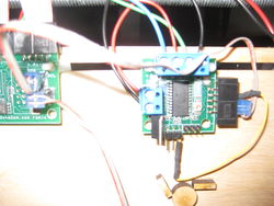
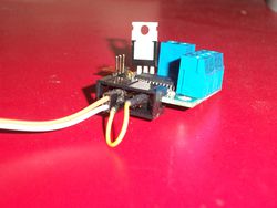
The process of connecting the Stepper controller to the Extruder stepper motor is fairly easy. Instead of hooking the SCA/SCL pins from the mainboard to the D9/D10 pins on the extruder board, you hook them to the step and direction pins on the Stepper Controller, as shown on the photos on the left and right (on the left, it is the cable that comes up too close and goes out of focus). You also need to connect the enable pin to ground on the stepper controller. I do this with a jumper wire from the max ground to the enable pin on the controller, it is the single yellow wire in the photos, there is a photo below, which shows the ground being connected to a ground pin on the ten pin connector.Polarity on the 2 pin wire is important, but if you hook it up backwards, it just won't turn the motor as it should and you can reverse the wire.
Connecting the power and the motor wires to the stepper controller is the same as it is on all of the Axis stepper controllers.
You can take a stepper motor from one of your axis (like the Z axis), temporarily, and connect it in this way, to see how different your extruder performs. I think you will be pleasantly surprised.
Here are some more photos to help with the details.
