Generation 3 Electronics
Contents
Generation 3 Electronics
Safety Tip
Once you start putting electricity into your RepRap - even at just 12 volts - you have to take basic, common sense precautions to avoid fires. Just in case these fail, test your workshop smoke detector. Got no smoke detector? Get one!
Overview
The electronics are the 'brain' of the system. They control all the various motors and actuators, read all the various inputs (endstops, temperature, etc) as well as communicate with the host system to get directions, report status, etc. The Generation 3 electronics are our latest attempt at improving these systems. The stepper drivers are smaller, more powerful and cheaper. The main processor has been upgraded from an atmega168 (Arduino) to and atmega644p (Sanguino). Likewise, the extruder controller boards have been consolidated onto a single board which itself contains an atmega168 (Arduino) which allows it to pursue its own individual tasks without the constant attention of the main board. The Generation 3 electronics also introduces an RS485 communications bus which allows the Motherboard to talk to the various extruder controllers in a nice, simple way.
Power Supply

Every machine needs a regulated power supply giving at least 8 amps at 12 volts. The easiest way to do this is to use a standard ATX power supply. Its simple, cheap, and all the boards are designed to accept the standard Molex connectors that are common on ATX power supplies. The new Motherboard has a connector that accepts the large 20-pin ATX power supply connector. The motherboard can even tell the power supply to turn on and off if needed.
Individual Boards
Parts List
<iframe width='500' height='300' frameborder='0' src='http://spreadsheets.google.com/pub?key=pmEMxYRcQzzATwbOb71BmGA&output=html&gid=30&single=true&widget=true'></iframe>
RepRap Motherboard

Stepper Motor Driver v2.3
<div class="thumb tright"></div>Each stepper driver board drives one of the stepper motors. You need three of these boards for a fully functioning RepRap. Each board controls the position of one axis. Together, they position the print head anywhere in the 3 dimensional build area. The stepper motor driver boards drastically simplify the control of stepper motors and provide a simple, standard interface.
More info and build instructions here.
Opto Endstop v2.1
<div class="thumb tright"></div>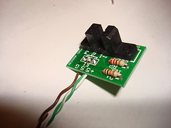
All of a RepRap's axes all need a datum (also known as home position or end-stop) to reference their movements. At the start of each build each axis needs to back up until the datum point is reached. We use one opto-switch for each axis to define its position. This page tells you how to wire one up.
More info and build instructions here.
Extruder Controller v2.2
Optional Boards
These boards are not required, but can be used to improve your machine or do different things.
Thermocouple Sensor v1.0
<div class="thumb tright"></div>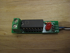
The thermocouple sensor is a different type of temperature sensor board. Unlike the thermistor based temperature sensor which can only really handle temperatures up to 300C, the thermocouple sensor can handle temperatures up to and over 1000C. It uses a thermocouple for temperature measurement, and it is much easier to read values from (as well as being a bit more accurate over a wider range.
Pro's: This board may be especially interesting if you're tight on memory space on the Arduino, using the thermocouple will allow you to leave out thermistor conversion tables. It also saves you the hassle of calibrating a thermistor. It will probably give a more accurate result (within 1-2 'C).
Con's: Unfortunately, it is also more expensive (by about $25)
More info and build instructions here.
Magnetic Rotary Encoder v1.0
<div class="thumb tright"></div>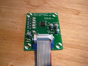
The magnetic rotary encoder is an optional board to determine the rotational speed of the extruder motor. A different method is laser-cut version, using a H21L0I (also used for endstops).
Pro's: Allows you to achieve better print quality than with open-loop controlling (without feedback) of the extruder motor.
Con's: Slightly added complexity due to another board in the system. The costs. Also, this board is surface mounted technology (SMT), which is slightly harder to solder and needs some extra (inexpensive) tools, such as a flux pen.
More info and build instructions here.
Wire It Up
The Generation 3 electronics attempts to address the wiring problems of Generation 2. Most of the cables have been connectorized, so it is fairly plug and play. The motherboard has IDC headers for all the stepper drivers, and jacks for the extruders to plug into. The stepper drivers and opto endstops use common ethernet patch cable for connections as does the extruder system. The end result is that hooking everything up is actually really easy.
Mounting and Wiring
First, find or cut a flat piece of thin plywood, about 300mm x 300 mm (12" x 12").
Next, place all your boards on the wood so that each board is close to where it will be wired to. Mark with a pencil through each hole, and also optionally around each board for drill holes and as a board outline.
Then, take all the boards off and drill a blind hole at each drill mark with a 2mm drill bit. (Use 3mm if you want to use nuts and bolts and drill right through - see below.)
Take a foot or so of silicone aquarium tubing and cut 5 mm (1/4") lengths of it. You will be using these to mount the boards to the wood. Optionally, you can use spacers if you want a more professional look.
Mount each PCB on the board using small round-headed woodscrews. Use the lengths of silicone tube as spacers between the wood and the PCBs.
Alternatively, mount each board on to the wood with M3 x 15mm bolts. Use washers on both sides, and use a short piece of tubing between the board and the wood for spacing (and shock absorbtion). Tighten down the nut by hand, and then a little bit with pliers or a wrench. It should be solidly attached, but not wrenched down too much. (For the brits: dont use too much welly ;)
Electronics distributed around the machine.
There are U-shaped PCB clamps in the RP parts for RepRap. These allow PCBs to be clamped to the 8mm rods that form the frame.
X, Y, and Z are the stepper controls for those axes. M is the microcontroller (this is the Sanguino, but the Arduino goes in the same place). The extruder control boards are at E behind the X stepper on the carriage.
Lasercut kits may use cable-ties, or excess small clamps normally used for clamping drive chain or drive belts.
Setup the Software
The recommended software is the R3G firmware on the motherboard/extruder controllers and ReplicatorG as the host controller software. It is possible to use others, but those are the easiest.
Please see the R3G software page for more information on how to install and configure those two pieces of software.