Gen7 Board 1.3.1/fr
Gen7 Board 1.2 | Gen7 Board 1.1 | Gen7 Board 1.0
This supersedes Gen7 Board 1.3.
Release status: working

| Description | Generation 7 Electronics
|
| License | |
| Author | |
| Contributors | |
| Based-on | [[]]
|
| Categories | |
| CAD Models | |
| External Link | (none)
|
Contents
Acheter les circuits et composants
Circuits imprimés
Vous pouvez acheter les circuits imprimés directement auprès de Traumflug.
Gen7 est conçu pour être fabriqué sur une RepRap, vous pouvez faire vous-même le circuit imprimé. La fabrication sur une RepRap ou une fraiseuse a commande numérique est décrite sur la page principale Gen7. Vous devez constuire un circuit "Gen7Board" PCB et jusqu’à 6 circuits "Endstop".
Une autre façon est d'acheter les circuits dans de nombreuses maisons spécialisées dans la fabrication des circuits imprimés. Gen7 est simple face, et donc cela ne coûtera pas une fortune. Si vous voulez vendre des copies , demandez a Traumflug pour une licence commerciale.
Composants
Vous pouvez obtenir un kit de composants Gen7et un kit de conencteurs Gen7 auprès de Traumflug.
Si vous souhaitez acheter vous même les composants et connecteurs, consultez la section Listes de pièces #Parts Lists.
Liste des pièces
Pour assembler ou de vérifier ces listes, ouvrez la mise en page avec gEDA / PCB et de l'exportation une «nomenclature». Cela vous donnera une liste de tous les composants nécessaires.
Considérations particulières:
- The Pololu Stepper Drivers want two single rows of 8 pin female connectors soldered into the board, so get these.
- Les drivers de moteur pas à pas de marque Pololu sont vendus avec les connecteurs males, il n'y a donc pas besoin de les acheter séparément..
- N'oubliez pas les 8 à 9 jumpers..
- Les résistances ont toutes une puissance de 0,25 W , même si le nom sur le circuit précise «0,125».
- The Pololus can be operated with up to 35 V, so you may want like-rated electrolytic capacitors.
- Vous pouvez ajouter dans la liste quelques câble pour les connecteurs, des broches supplémentaire à sertir et quelques fils.
Composants électroniques
La liste est ordonné dans le même sens que l'assemblage.
| Name | Count | Designations | Vendors | Remarks | |||||
|---|---|---|---|---|---|---|---|---|---|
| 0.6 mm Wire | 50 cm | Völkner | Digi-Key | Mouser | for the wire bridges on single sided PCBs | ||||
| Resistor 560 Ohms | 2 | R14, R22 | Reichelt | Völkner | Farnell | RS | Digi-Key | Mouser | |
| Resistor 1 kOhms | 8 | R2, R6, R8, R10, R11, R12, R16, R18 | Reichelt | Völkner | Farnell | RS | Digi-Key | Mouser | |
| Resistor 4.7 kOhms | 2 | RT1, RT2 | Reichelt | Völkner | Farnell | RS | Digi-Key | Mouser | |
| Resistor 10 kOhms | 1 | R30 | Reichelt | Völkner | Farnell | RS | Digi-Key | Mouser | |
| Diode 1N4004 | 2 | D1, D2 | Reichelt | Völkner | Farnell | Digi-Key | Mouser | ||
| Coil 100 uH | 1 | L1 | Reichelt | Völkner | Farnell | Digi-Key | Mouser | ||
| Crystal 16 MHz or 20 MHz | 1 | U6 | Reichelt | Völkner | Farnell | Digi-Key | Mouser | ||
| Reset Switch | 1 | RESET | Reichelt | Völkner | Farnell | Digi-Key | Mouser | ||
| Ceramic Capacitor 0.1 uF | 12 | C5, C8, C9, C10, C11, C12, C13, C14, C16, C17, C18, C19 | Reichelt | Völkner | Farnell | RS | Digi-Key | Mouser | |
| LED 3 mm Green | 3 | LED2, LED5, +5V | Reichelt | Völkner | Farnell | Digi-Key | Mouser | ||
| LED 3 mm Yellow | 1 | Standby | Reichelt | Völkner | Farnell | Digi-key | Mouser | ||
| Ceramic Capacitor 22 pF | 2 | C3, C4 | Reichelt | Völkner | Farnell | RS | Digi-Key | Mouser | |
| Electrolytic Capacitor 10 uF | 2 | CT1, CT2 | Reichelt | Völkner | Farnell | Digi-key | Mouser | ||
| Electrolytic Capacitor 100 uF | 4 | C1, C2, C6, C7 | Reichelt | Völkner | Farnell | Digi-Key | Mouser | ||
| Jumper Header 2 Pin Pairs | 4 pair | J2/J3, J5/J6, J8/J9, J11/J12 | Reichelt | RS | Digi-Key | Mouser | cut them into appropriate pieces | ||
| Jumper Header 2 Pin | 3 | J13, J14, J15 | Reichelt | Völkner | RS | Digi-Key | Mouser | cut them into appropriate pieces | |
| Jumper for the two above | 9 | Reichelt | RS | Digi-Key | Mouser | ||||
| ICSP Header | 1 | CONN6 | Reichelt | RS | Digi-Key | Mouser | alternatively, assemble this out of the remainings of the Jumper 2 Pin Headers | ||
| Pololu Header | 8 or 4 | U2, U3, U4, U5 | Reichelt | Völkner | Digi-Key | Mouser | cut them to appropriate length, you want 8x 8 pins | ||
| Misc Header | 1 | MISC | Reichelt | Völkner | Digi-Key | Mouser | cut to appropriate length | ||
| Socket for the ATmega | 1 | U1 | Reichelt | Völkner | Farnell | Digi-Key | Mouser | ||
| ATmega 644 (or 644P) | 1 | Reichelt | Farnell | Digi-Key | Mouser | ||||
| MOSFET IRFZ 44N | 2 | Q1, Q2 | Reichelt | Völkner | Farnell | RS | Digi-Key | Mouser | |
Connecteurs
| Name | Count | Designations | Vendors | Remarks | |||||
|---|---|---|---|---|---|---|---|---|---|
| Motor Header Molex 26-48-1045 (4 Pin) | 4 | X_MOT_0.156, Y_MOT_0.156, Z_MOT_0.156, E_MOT_0.156 | RS | Digi-Key | Mouser | This is the one also used in Gen2 and Gen3 Electronics; | |||
| Cable Connector for the above | 4 | RS | DigiKey | Mouser | |||||
| Crimp Contact for the above | 16 | RS | DigiKey | Mouser | |||||
| Alternative to Motor Header: 4 Pin Screw Terminal | 4 | X_MOT_0.156, Y_MOT_0.156, Z_MOT_0.156, E_MOT_0.156 | Reichelt | DigiKey | Mouser | ||||
| Heater Header Molex 26-48-1045 (2 Pin) | 2 | HEATER1, HEATER2 | RS | DigiKey | Mouser | ||||
| Cable Connector for the above | 2 | RS | DigiKey | Mouser | |||||
| Crimp Contact for the above | 4 | RS | DigiKey | Mouser | same as the one for the motor headers | ||||
| Alternative to Heater Header: 2 Pin Screw Terminal | 2 | HEATER_1, HEATER2 | Reichelt | DigiKey | Mouser | ||||
| Disk Power Header | 2 | CONN2, CONN3 | Reichelt | RS | DigiKey | Mouser | also see DIY 4 pin molex connector | ||
| ATX24 Power Connector | 1 | CONN1 | RS | DigiKey | Mouser | Molex Mini-Fit 44206-0007 | |||
| Molex KK100 2 Pin Header | 2 | TEMP1, TEMP2 | Reichelt | RS | DigiKey | Mouser | |||
| Cable Connector for the above | 2 | Reichelt | RS | DigiKey | Mouser | ||||
| Crimp Contact for the above | 4 | Reichelt | RS | DigiKey | Mouser | ||||
| Molex KK100 3 Pin Header | 6 | X_MIN, X_MAX, Y_MIN, Y_MAX, Z_MIN, Z_MAX | Reichelt | RS | DigiKey | Mouser | Reichelt are tested to be fully compatible with Molex | ||
| Cable Connector for the above | 6 | Reichelt | RS | DigiKey | Mouser | ||||
| Crimp Contact for the above | 18 | Reichelt | RS | DigiKey | Mouser | same as for TEMP1, TEMP2 above | |||
| Molex KK100 6 Pin Header | 1 | SERIAL | RS | DigiKey | Mouser | alternatively, use the same as for Jumper 2 Pin | |||
| Optional: Cable Header for the above | 1 | RS | DigiKey | Mouser | only needed if you intend to solder your own USB-to-TTL cable | ||||
| Option: Crimp Contact for the above | 6 | RS | DigiKey | Mouser | only needed if you intend to solder your own USB-to-TTL cable | ||||
| Radiateurs pour les MOSFETs | 2 | Reichelt | RS | DigiKey | Mouser | Please note that Reichelt ones are quite wide (26mm). Two of them won't fit on 1.3 | |||
| Vis Chc M3 x 8 mm pour le montage des radiateurs sur les MOSFET | 2 | ||||||||
| Rondelle M3 pour le montage des radiateurs sur les MOSFET | 2 | ||||||||
| Ecrous M3 pour le montage des radiateurs sur les MOSFET | 2 | ||||||||
| Radiateur pour les polulus | 4 | Völkner | RS | ||||||
| Ruban double face conducteur de la chaleur | 1 | Völkner | pour le double face qui permet de coller els radiateurs sur les polulu, coupé le à la bonne dimension. | ||||||
Miscellaneous
L'électronique de la Génération 7 utilise un port série pour les communications avec le PC. Les PC modernes n'ont plus cette connexion, il faudra utiliser un adaptateur USB /TTL. Vous pouvez trouver ce composants ici:
| USB to TTL Cable | DigiKey | Mouser | Adafruit Industries | MAKE Store | MakerBot Industries | Watterott |
|---|
Une alternative au cable l'USB/TTL câble est une petite carte électronique:
| USB to TTL Breakout Board | Watterott | Sparkfun |
|---|---|---|
| Cable for the above | Watterott |
Une autre alternative E'go USB-TTL adapter, voir instructions et limitations.
Enfin et surtout, vous aurez besoin de quatre drivers de moteurs pas à pas:
| Pololu A4983 Breakout Board | Pololu |
|---|---|
| Open Source Alternative | StepStick |
Instructions pour le montage
- Pour connaître les composants à mettre où, avoir la présentation sur votre écran de PC disponibles.
- Les circuits imprimées fabriquées avec des chemins de Voronoi ont besoin de plus de chaleur, augmenter la température de votre fer à souder d'environ 20 degrés Celsius.
- Commencez par les composants les plus plats, généralement les ponts de fil et les résistances. De cette manière, les composants ne tombent pas quand vous posez le circuit imprimé face soudure vers l'avant pour la soudure. Ensuite, continuer avec des pièces de plus en plus haute, vous finirez par les connecteurs.
- La liste des pièces est triée dans cet esprit, il suffit de commencer par les composants du haut et de suivre vers le bas.
- Pour faciliter le maintien des cavaliers et des composants similaires, mettre une petite goutte de colle cyanolite sur le côté composant avant de les insérer. Comme la carte est recto seul, cela ne nuira pas au fonctionnement.
- La bobine 100 uH ressemble à une résistance. Elle est un peu plus épaisse et contient des anneaux brun-noir-brun.
- Comme huit têtes de broches pour le Pololus sont chers, les kits sont livrés avec têtes à moindre coût la broche 10. Couper 2 broches hors de chacun.
- Bien souder une paire de ces en-têtes, insérer un Pololu pour assurer un bon alignement.
Attention : Ne pas souder les MOSFETs et n’insérez pas encore le ATmega avant de faire les vérifications d'alimentations.
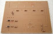
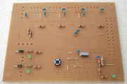
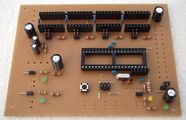
Assemblage en photos
Cliquez sur les photos pour voir en plus grand.
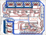
Si vous êtes incertain, se référer à cette image qui précise la disposition des composants. Les désignations correspondent à ceux de la liste des pièces.

Pour une meilleure qualité, soudez de l'étain sur tous les points de soudure avant d'insérer les composants.
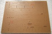
Commencez avec les 9 ponts. Ils sont représentés par des pistes vertes mates sur le graphiques de présentation.

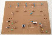
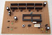
R14 et R22 ont 560 Ω,de couleur vert-bleu-marron.
Les 8 autres résistances de R2 à R18 sont de 1 kΩ , code couleur brun-noir-rouge.
Près du connecteur thermistance il ya deux résistances RT1 et RT2 de 4,7 kΩ : jaune-violet-rouge.

La dernière des résistances est R30 de 10 kΩ , codé marron-noir-orange.
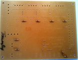
D1 et D2 sont des diodes, vous devez prendre soin de la polarité. Les diodes ont un anneau blanc, qui doit se retrouver le plus près du bord du circuit.
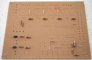
L1 ressemble à une résistance, mais c'est en réalité une bobine. Le sens de l'insertion n'a pas d'importance ici.
U6 est le quarz pour l'horloge de l'ATmega. Insérez-le dans n'importe quel sens, mais essayez de chauffer chaque point de soudure pas plus de 3 secondes.

L'interrupteur de réinitialisation peut se monter dans les 2 sens
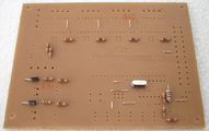
Maintenant c'est le bon moment pour insérer les 12 condensateurs de suppression du bruit. Encore une fois, la direction n'a pas d'importance.
LED2, LED5 et le +5 V LED sont des LED vertes. Les LED sont des diodes, il faut donc bien les orienter. La plus grande des 2 pattes est associé au signe +, qui arrive d'aller dans le trou supérieur à chaque fois. Vous pouvez aussi comparer avec le signe + du schéma d'implantation.

Idem pour la LED pour la veille, la patte la plus longue va dans le trou supérieur
les condensateurs C3 et C4 font osciller le quartz. Pas de sens d'insertion.

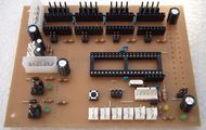
CT1 et CT2 sont des condensateurs électrolytiques, qui ont une polarité. La bande blanche sur le condensateur précise la polarité moins (-) et va dans le trou inférieur.

C1, C2, C6 et C7 sont des condensateurs électrolytiques, la broche (-) va à l'extérieur ou vers le bas. Encore une fois, comparer avec du schéma d'implantation.
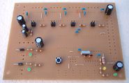
Maintenant, insérez les support pour les cavaliers du Pololu. Pas de polarité. Au montage, vous pouvez les coller sur le circuit avec une petite quantité de colle cyanolite, appliqué à la partie plastique uniquement, cela facilite le montage.

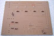
Dans le coin inférieur droit, il y a trois connecteur en paires unique.

Le connecteur avec trois paires est utilisée pour connecter le programmeur
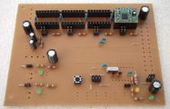
Changing the appearance of the board quite a bit, insérez les 8 connecteurs femelle pour les Pololus. Probablement que vous aurez besoin de les couper en longueur (utilisez une paire de ciseaux). C'est aussi une bonne idée d'insérer un driver Pololu avec ces 2 connecteur mâle pour assurer un parfait ajustement des connecteurs femelles.

The Misc header currently isn't that important, insert it for completeness.
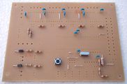
La dernière partie des composants commence par est le connecteur de l'ATmega. Celui ci s'insère sur son support ( a ne pas faire dès maintenant). Soudez d'abord les broches dans les coins, puis souder les autres broches. Cela assure un bon ajustement et une distribution de chaleur modérée..
First of the connectors may be the serial one. The snap is on the side closer to the ATmega socket.

Deux connecteurs pour connecter les thermistances.

Six connecteurs pour les fins de course. Orientez le connecteurs avec le loquet à droite, pour être compatible avec tous les autres connecteurs.

Les connecteurs pour les chauffages (extrudeur et plan de travail) et le moteurs sont plus gros. Veillez à utiliser suffisamment de soudure, car ils passe beaucoup plus de courant.
La carte est fournie avec la possibilité d'alimentation à travers les connecteurs de puissance type Molex. Encore une fois, ne pas économiser sur la soudure.
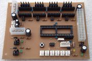
Le dernier connecteur est l'ATX24. Pour l'instant, vous avez terminé avec la soudure.
Concours a celui qui fera les meilleurs soudures !


Comme vous pouvez le voir, ni les MOSFETs, ni l'ATmega ne sont insérés encore. Nous y reviendrons plus tard.
Mise en route
Ces étapes montrent comment passer d'une carte mère soudé a un statut opérationnel.
Alimentation possible
Vous pouvez alimenter la carte de plusieurs manière.

Option 1
C'est celle qui est recommandée. Prenez une alimentation de PC et branchez le connecteur ATX24, ainsi que les deux connecteurs d'alimentation du disque.
Les alimentation de PC ont deux câbles avec plusieurs connecteurs d'alimentation. Chacun de ces câbles peut fournir environ 10 ampères, assurez-vous de brancher un seul connecteur de chaque câble sur la Gen7.
Dans ce scénario, l'ATmega peut fonctionner et communiquer avec le PC en mode "off" (en mode veille). Donc, ne soyez pas surpris si vous commencez à travailler avec votre Mendel et que l'alimentation est encore calme. Chaque commande G-code nécessitant plus de courant va faire tourner l’alimentation de suite.
Note: le connecteur ATX24 est rétrocompatible avec les anciens connecteurs ATX20, donc si vous avez un bloc d'alimentation avec un connecteur ATX20, vous pouvez l'utiliser. Il n'y a qu'une seule position d'insertion, et donc pas d'inconvénient à utiliser un vieux approvisionnement.
Option 2
C'est pour les utilisateurs qui utilise une alimentation non-PC. Vous utiliserez uniquement les 2 connecteurs MOLEX qui fournissent du 5V et du 12V. Le connecteur ATX24 est laissé vide.
Aucune fonction de veille ici. l'ATmega, les Pololus, les moteurs et chauffages sont alimentés tout le temps.
Option 3
Cela permet de faire fonctionner l'ATmega uniquement. Cela peut être utile pour la programmation du firmware. Laissez le ATX24 ainsi que les deux têtes d'alimentation du disque vide. L'ATmega sera alimenté par le connecteur de la liaison série. Cela suppose que votre connecteur série puisse fournir 5V , certains convertisseurs USB-TTL necessite de souder une broche pour activer cette fonction.
Cette option ne permet pas de déplacer les moteurs ou de chauffer l'extrudeuse.
Sélection de la source d'alimentation
Après avoir choisi une option pour l'alimentation, vous devez spécifier au système où obtenir il peut obtenir le 5 V.

Dans le coin inférieur droit de la carte, vous verrez trois cavaliers.
- ATX24: pour l'option 1.
- Disk Power: pour l'option 2.
- Serial: pour l'option 3.
Vous devez installer un cavalier, et un seul.
Contrôle d'alimentation
Utiliser le cavalier correspondant au choix d'alimentation. Vous pouvez prendre quelques mesures pour s'assurer que votre nouveau ATmega sera ne va pas griller lors de l'insertion.

- Rouge: alimentation insérés en fonction de n'importe quelle option. En cas d'option 1, l’alimentation n'est pas encore activé.
- Bleu: comme ci-dessus, avec alimentation activé ou d'alimentation en fonction de l'option 2. Non applicable à l'option 3.
Remarque: dans l'image ci dessus, il n'y a pas de cavalier 5 V, mais vous devez avoir mis un cavalier qui précise l'option que vous désirez utiliser.
Checks:
- Pas de fumée? Super.
- Le voyant jaune dans le coin inférieur droit est allumé? Encore Super.
- Si vous avez choisi l'option 1, cour-circuiter les deux ponts de fil, comme sur la ligne pointillée verte dans l'image. Ceci devrait activer l'alimentation.
- Dans le même temps, la LED verte dans le coin inférieur droit devrait être allumée
- Si vous avez un voltmètre, mesurer les tensions montrées sur la photo.
- Vérifiez chacune des broches de la prise ATmega, aucune d'entre elles ne devraient avoir plus de 5,5 volts.
- Pour plus de sécurité, vérifiez les broches de la rangée inférieure des connecteurs pour les Pololus. Aucun d'entre eux devrait dépasser 5,5 volts aussi.
Si vous avez respecter toutes ces recommandations, vous pouvez sans risque passer à la suite.
Insertion des Semiconducteurs
Maintenant c'est le bon moment pour inserer les semi conducteurs, si toutes les étapes précédentes ont bien été respecté

- Débranchez l'alimentation électrique entièrement.
- Soudez les MOSFET à leur place avec le côté plat vers le centre du circuit. Utilisez suffisamment de soudure , les courants sont élevés ici.
- Montez les radiateurs. La photo montre le placement recommandée.
- Insérez le ATmega dans son socket. Il y a une encoche sur l'une des extrémités du boitier noire du processeur (groove) . Cette rainure doit être du coté des transistors MOSFET , l'autre partie sans l'encoche est proche du connecteur ATX24.
Prepare your Arduino IDE
- Download and unpack or install the Arduino IDE.
- Download and unpack the latest Gen7 Arduino IDE Support package.
- Find the folder
Gen7in this package and move it into thehardwarefolder inside the Arduino package. There are also install instructions inside the Gen7 Arduino IDE Support package. - Fire up your Arduino IDE.
- Under Menu -> Tools -> Board, select your variant of Gen7 board (there should be four new entries). They differ in processor type and clock speed.
- Under Menu -> Tools -> Serial Port, select the correct serial/com port.
Note: for Linux/Unix users, if you install using your package manager it may be difficult to find your arduino/hardware folder, and even after you find it you might not be able to copy to it. Just make a "hardware" folder in the "sketches" folder of your home directory and put the Gen7 support folder in there. The "sketches" folder appears when you run the IDE the first time.
Bootloader
If you bought your ATmega with one of the Gen7 kits, the bootloader should have already been uploaded. Any other bootloader, like the one used for the Sanguino, RAMPS, Sanguinololu or whatever is also fine.
If you bought a factory fresh ATmega, e.g. from a general electronics supplier, see the Bootloader Upload section below.
If you're in doubt, just continue with the setup. A missing bootloader will result in a timeout error when attempting to upload a firmware.
Serial Connection
It's recommended to either use a USB to TTL cable or USB to TTL breakout board. Custom solutions are possible, see Customisations.
Here's how you connect them, GND is always the pin to the left:


Simply plug the connector in, connect USB to your PC and a new serial port should show up in your PC's operating system.
Your First Firmware Upload
After all this assembling, and with this complex firmware thing ahead, whouldn't it be a good idea to upload some test firmware to test wether basic things work? Of course!
You can find such a test firmware in Gen7's Github repository.
- Download that file SetupText.pde. If it opens in the browser window, do a "Save as...".
- Prepare your Gen7 by inserting power plugs, the serial converter, the USB plug of that converter and so on.
- Start your Arduino IDE.
- With the IDE, open SetupTest.pde. You'll be asked if you want to create a folder of the same name, click "Yes".
- Make sure the right serial port and the right type of board is still selected in the Test menu.
- Hit the "Upload" button (the second from the right).
After a second or two, you should see something like
Binary sketch size: 2142 bytes (of a 63488 byte maximum)
in the black text field, and after another second of blinking on the serial connector, it should say "Done uploading." right above that text field.

Now you can safely assume uploading a firmware works. The test firmware has a few more features:
- If you open the IDE's serial monitor and listen at 9600 baud, you can read what the ATmega is doing. If you can read clear text, the serial line is working.
- Three or four seconds after the upload, the power supply should spring to life, blink the LED of HEATER1 a few times and turn the PSU off again.
- The same happens after each hit of the Reset button on the board, independently from the IDE or the serial connection.
Microstepping
Last not least, you probably want to set up microstepping to something other than the default. The default is halfstepping. Smaller microsteps make the motors run smoother, but also raise the computing load for the ATmega. The smallest steps possible are 1/16 microstepping.
Feel free to select different settings for each of the motors, e.g. 1/8 microstepping for threaded rod axes (Z) and 1/16 microstepping for belt driven axes (X, Y).
Selecting microstepping is done with the jumpers in front of each of the Pololus, they refer to MS2 and MS3. Allegro documents also know about MS1, which is hard wired to High in Gen7. Plugging a jumper sets High, while leaving the header free sets Low. Here's a detail picture of a Gen7, with MS2 set to High, MS3 set to Low:

The following table shows what you get with each combination:
| MS2 | MS3 | Microstep Resolution |
|---|---|---|
| Open | Open | Half step |
| Open | Plugged | Not allowed! |
| Plugged | Open | Eighth step |
| Plugged | Plugged | Sixteenth step |
Firmware
In principle, you can run any of the RepRap Firmwares on this board. Adjust the I/O pin layout, adjust compile time options for no secondary board/no RS485 and proceed. Just like Gen2, RAMPS or similar electronics.
Teacup Firmware
Teacup's Simple Installation instructions show nicely how to do this. Some tweaks are required for Gen7:
- Have your Arduino IDE prepared for Gen7, as explained above.
- Download the Gen7 branch instead of the standard download.
- Use the config.gen7.h and ThermistorTable.gen7.h you find there.
With config.h left untouched, at least something should move. This is fine for first tests, but not sufficient to have everything right for your machine. Edit your config.h further to match your machine and your setup. Config.h has a lot of comments inside the file, helping on the details. For example, STEPS_PER_MM_X should be set according to your choice of microstepping.
FiveD Firmware
FiveD has been run succssfully on Gen7. As the ATmega pin layout of v1.3 almost matches that of v1.2, firmwares running on v1.2 continue to work on v1.3. Snuggles has kindly contributed his sources:
File:FiveD 20100610 for Gen7 v1.2.zip
To upload the Firmware do the following:
- Have your Arduino IDE prepared for Gen7, as explained above.
- Open the FiveD_GCode_Interpreter.pde file inside the FiveD_GCode_Interpreter folder with the IDE.
- Press the upload button in the IDE's toolbar.
- If there are no errors, you're done.
This should get you started, but don't forget to adjust STEPS_PER_MM in configuration.h to match your mechanics.
Other Configurations
The following should help to configure other firmwares.
Pinout

| Function | ATMega Name | Teacup | Original firmware | Direction in firmware |
|---|---|---|---|---|
| X Step | PC3 | DIO19 | 19 | Digital Output |
| X Direction | PC2 | DIO18 | 18 | Digital Output |
| X Min | PB7 | DIO7 | 7 | Digital Output |
| X Max | PB6 | DIO6 | 6 | Digital Output |
| Y Step | PC7 | DIO23 | 23 | Digital Output |
| Y Direction | PC6 | DIO22 | 22 | Digital Output |
| Y Min | PB5 | DIO5 | 5 | Digital Output |
| Y Max | PB2 | DIO2 | 2 | Digital Output |
| Z Step | PA5 | DIO26 | 26 | Digital Output |
| Z Direction | PA6 | DIO25 | 25 | Digital Output |
| Z Min | PB1 | DIO1 | 1 | Digital Output |
| Z Max | PB0 | DIO0 | 0 | Digital Output |
| Extruder Step | PA3 | DIO28 | 28 | Digital Output |
| Extruder Direction | PA4 | DIO27 | 27 | Digital Output |
| Power Enable | PD7 | DIO15 | 15 | Open Drain Output, active low |
| Motors Enable | PA7 | DIO24 | 24 | Digital Output |
| Heater 1 | PB4 | DIO4 | 4 | Digital Output |
| Heater 2 | PB3 | DIO3 | 3 | Digital Output |
| Temp 1 | PA1 | AIO1 | 1 | Analog Input |
| Temp 2 | PA2 | AIO2 | 2 | Analog Input |
Changes from v1.2:
- Fan 1 (PA0 / DIO31 / 31) is gone.
Customisations & Others
This part describes possible modifcations for advanced users only.
Non-12-V-Voltages
While it's very practical to use 12 volts as they come out of the power supply, Gen7 is prepared for other voltages, too. Even better, you can supply different voltages for motors and heaters.
Possible usages:
- 12 V for the heaters, 24 for the motors. This will still allow to use standard Reprap heating elements for the extruder and heated bed, while the motors can now run faster. Motor supply voltage is only limited by the Pololus and can go up to 35 volts.
- 12 V for the motors, 5 V for the heaters. This whould wear your power supply more evenly.
- 12 V for the motors, 3.3 V for something like EDM or inductive heated nozzles. Remember, the IRFZ44N can switch pretty fast, and the ATmega has frequency/PWM generators on board.
- ...
On where to supply what, see the picture above. Simply rewire the disk power connectors to your needs and make sure all power sources contact at least one GND pin, to give them a common ground.
The 5 volts on the upper disk power connector is not needed if you use the ATX20/24 connector, but don't supply there a different voltage, or a voltage from a different power supply, either.
Serial Connection
If you want a custom solution, you can create one, of course. Just connecting an RS-232 port to the serial connector won't work, however, even if you ignored the different voltage levels. ATmega's serial signal is inverted (Logical 0 = 5V, Logical 1 = 0V). Here's the serial connector's pinout:

| 1 | 2 | 3 | 4 | 5 | 6 |
|---|---|---|---|---|---|
| GND | CTS (set to GND) | +5 Volts | RxD | TxD | Reset |
RxD is ATmega's pin 14 (data to the chip); TxD is ATmega's pin 15 (data from the chip).
With pin 3 you can feed the ATmega, if you have no other current source. If you have another current source, e.g. your power supply, you might have slightly different potentials of 5V though, so you better keep this pin unconnected.
Pin 6 is usually connected to the serial line's RTS. This triggers a reset each time you start a connection to the ATmega and is very convenient when uploading firmware - no pressing of the reset button needed, then. Arduinos have this hardwired. If you keep pin 6 free, press the reset button each time your IDE (avrdude) attempts an upload.
Using an E'go USB-TTL adapter
This converter is cheap, uses the Silicon Labs CP2102 chip and basically works:

| Gen7 | GND (Pin 1) | +5 Volts (Pin 3) | RxD (Pin 4) | TxD (Pin 5) |
| USB-TTL adapter | GND (Pin 5) | +5 Volts (Pin 6) | TxD (Pin 3) | RxD (Pin 4) |
Important here is to not connect both Reset pins.
What you can't get is auto-reset. So you have to press the reset button when uploading a firmware.
Bootloader Upload
Note: this section only applies if you have a blank, factory fresh ATmega on your board. Friendly Gen7 vendors will do these steps for you before shipping, so you don't need a programmer.
This section describes how to program the bootloader using a programmer. These programmers usually cost some $20 to $30. Even cheaper is to build a bit banging parallel port adapter. Another alternative is to use an Arduino or second electronics as a programmer.
How to go:
- Disconnect all connectors, including the power supply.
- Insert the ATmega644 into it's socket. Make sure you do it the right way, the small nut on the housing goes towards the heater connectors, the numbers on the housing can be read looking from the ATX20 connector side.
- Re-connect the power supply.
Note: The pins used for the programmer conflict with the pins used for the X_MAX, X_MIN and Y_MIN endstops. This isn't an issue in normal operation, but make really sure you have these endstops disconnected before hooking up the programmer.
- Connect your programmer. Again, watch out for insertion of the plug the right way.
Now you should see something like this - the red LED indicates the PSU is still without juice:

Programming the bootloader using the command line
- Have your Arduino IDE prepared for Gen7, as explained above.
- Connect your power supply, at least one of the power connector indicators should be lighted.
- Open a terminal and change directory into Arduino IDE's folder. All required tools are there, even if you haven't installed them system-wide.
Linux
The following sequence was done on Linux and should apply similarly on other OSs.
cd hardware/tools
./avrdude -C ./avrdude.conf -c ?  # find your programmer, e.g. "avrispv2"

### For the ATmega644:
# write fuses
./avrdude -C ./avrdude.conf -c <your programmer> -p atmega644 -P /dev/ttyACM0 \
    -B 5 -U lfuse:w:0xF7:m -U hfuse:w:0xDC:m -U efuse:w:0xFC:m
# upload bootloader
./avrdude -C ./avrdude.conf -c <your programmer> -p atmega644 -P /dev/ttyACM0 \
    -B 1 -U flash:w:../Gen7/bootloaders/Gen7/bootloader-<your variant>.hex
# lock the bootloader
# this gives an expected "verification error 0xcf != 0x0f"
./avrdude -C ./avrdude.conf -c <your programmer> -p atmega644 -P /dev/ttyACM0 \
    -B 1 -U lock:w:0xCF:m

### For the ATmega644P:
# like above, but swap "-p atmega644" with "-p atmega644p"
Watch your programmer a few seconds blinking and you're done. Note that if you're using the Arduino as programmer, you may need to add the flag "-b 19200" for it to work correctly.
Windows
On Windows, you'll have to find out which COM port your board is connected to. Or simply try COM1 ... COM8 until it works. Similarly to the above, the commands on Windows are:
cd hardware\tools\avr\bin
avrdude -C ..\..\etc\avrdude.conf -c ?  # find your programmer, e.g. "avrispv2"

### For the ATmega644:
# write fuses
avrdude -C ..\..\etc\avrdude.conf -c <your programmer> -p atmega644 -P COM1 \
   -B 5 -U lfuse:w:0xF7:m -U hfuse:w:0xDC:m -U efuse:w:0xFC:m
# upload bootloader
avrdude -C ..\..\etc\avrdude.conf -c <your programmer> -p atmega644 -P COM1 \
    -B 1 -U flash:w:..\..\..\Gen7\bootloaders\Gen7\bootloader-<your variant>.hex
# lock the bootloader
# this gives an expected "verification error 0xcf != 0x0f"
avrdude -C ..\..\etc\avrdude.conf -c <your programmer> -p atmega644 -P COM1 \
    -B 1 -U lock:w:0xCF:m

### For the ATmega644P:
# like above, but swap "-p atmega644" with "-p atmega644p"
Watch your programmer a few seconds blinking and you're done.
Programming the bootloader using Arduino IDE
-- Yet to be found out --
Debugging hint: Arduino obviously doesn't attempt to use the "-B 5" flag when writing fuses onto a factory fresh chip. This is needed if the programmer was set to a higher speed earlier, as an ATmega running at 1 MHz (factory default) can't keep up with 115200 baud.
Specials
One user had a power supply delivering just 4.5 volts in standby. That's tight, because at 4.3 V the brown-out detector jumps in and resets the board.
To deal with this, you can change the extended fuse from 0xFC to 0xFD. This sets the brown-out detector's trigger level lower, to 2.7 V. While the ATmega will run out of specification for short periods of time, then, this is obviously better than no brown-out detector at all.
References
- AVR Fuse Calculator
- Check fuses and other ATmega properties with:
./avrdude -C ./avrdude.conf -c <your programmer> -p atmega644p -P /dev/ttyACM0 -n -v
- How to write the bootloader onto Arduinos
- Bootloader half the size of Arduino's/Sanguino's
- About programming with direct USB programmers like the USBTinyISP. Hint: you need to use "sudo" or write a rule in /etc/rules.d.