FoldaRap Build Manual
|
English • العربية • български • català • čeština • Deutsch • Ελληνικά • español • فارسی • français • hrvatski • magyar • italiano • română • 日本語 • 한국어 • lietuvių • Nederlands • norsk • polski • português • русский • Türkçe • українська • 中文(中国大陆) • 中文(台灣) • עברית • azərbaycanca • |
Contents
Tools required
- 2 mm Allen wrench (for M3 counterksunk bolts and pneumatic fittings "MA-12-03-M5")
- 2,5 mm Allen wrench (for normal M3 cap-head bolts and the rounded M4 bolts used for the frame)
- little flat screwdriver (for the screw terminals)
- something to cut wires, and something to strip them (knife, automatic striper, etc.)
- iron (to solder the plug and switch), and a lighter for the heat-shrink sleeves
Overview
The best way to get started is by starting from the source files : if necessary download sketchup, and the latest FoldaRap.skp, then you'll be able to navigate through the machine (folded/unfolded).
There is not yet a perfect build order. We will refine that over time (that's why the number of parts required for each step is separated from the pictures)
 (I wanted to make a Gantt diagram for that... here is a try)
This decomposition of the big steps in smaller tasks, allow you to see what are the role of each small tasks in the bigger picture. Basically we have a main frame and several sub-assemblies, some can be done in parallel - i.e : gather your friends and establish a record of minimum building time :)
Here is an overview of the steps that can't be done before others :
- Almost ready to print :D
- XZ-axis (2/2)
- turn the z-threaded rods in the x-ends to slide them through z-coupling
- add the z-couplings
- add the two z-motors
- X-end-motor
- fit the pulley to the 5mm motor shaft (use the included grub screw to lock it)
- X-end-idler-extruder
- add the bearing and it's axis (623 and a M3x12 screwed in the plastic will do the job)
- add the z-couplings
- turn the z-threaded rods in the x-ends to slide them through z-coupling
- electronic
- wiring
- finish by the bed wires (peltier and thermistor)
- hotend-end and thermistor
- motors and endstop (the wires are usually 80-100cm long, we will shorten them)
- Y-motor (20cm) and Y-endstop, X-motor (50cm) and X-endstop (50cm) and extruder motor (50cm)
- Z-motors (25cm) and Z-endstop (25cm)
- motors and endstop (the wires are usually 80-100cm long, we will shorten them)
- hotend-end and thermistor
- add the board-mount part to the board
- bolt the PSU on the plate
- finish by the bed wires (peltier and thermistor)
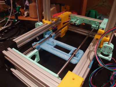
- Y-axis completed !
- Tighten the M3x15 bolts on the Y-idler and Y-motor to lock the smooth-rods.
- Tighten the belt by closing the loop with zip-ties.
- Slide the smooth rods through the Y-idler or Y-motor part, put the Y-carriage (aka frog) on the smooth rod and then finish to slide them through the other part. To align the Y-motor and Y-idler check that the carriage run smoothly. Since the Y-motor is already in the middle thanks to the 6mm bump on the small-left-foot, use the carriage to set the Y-idler's distance from each foot (expected to be ~12mm from each inner side), once satisfied you can lock them in place with their respective round M4x8.
- Y-idler, in place with 3 round M4x8 on the frame side away from you, between the bigger and strange feet (you'll see after that this shape allow to save space, ~62mm, when the machine is not deployed).
- put in place the 2 M3x15 and 2 M3 nut that will serve to lock the Y-smooth rods, but don't tighten them yet
- add two 623 bearing on the M3x25 bolt, and M3 nut, to make the idler (or 624 and M4 bolt)
- Y-motor, in place with 5 round M4x8 on the frame side near you, between the smaller feet.
- put in place the 2 M3x15 and 2 M3 nut that will serve to lock the Y-smooth rods, but don't tighten them yet
- attach the IEC female plug (need 2 countersunk M3x8-10 and 2 M3 nut) (the holes are for M4 but there is not enough space for an M4 nut), solder also the switch if you have one
- add the motor to the Y-motor (need 4 M3x10)
- fit the pulley to the 5mm motor shaft (use the included grub screw to lock it)
- add the motor to the Y-motor (need 4 M3x10)
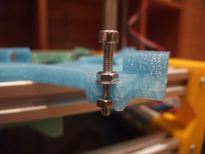
- Y-carriage with bed-plate, assemble them with the long M3x40 bolt (with washers, springs, nuts)
- Y-carriage
- put the 3 LM6UU bearings in the Y-carriage
- clamp the middle of the Y-belt with the y-belt-clamp
- Bed-plate
- Screw the wood-plate on the alu-plate with 4 countersunk M3x10 and 4 nylock nut,
- Put the wood-plate in place and insulate the underside with tape (kapton or whatever)
- Add the thermistor, as to be in a corner of the space left in the middle by the wood plate.
- Spread some heatsink compound then put the peltier on it, and use kapton tape to cover it from side to side of the alu-plate (the kapton will be kept in place by the wood-plate).
- Take the peltier cell, use it to trace the limits of its emplacement in the center of the alu bed (the center is at 70x70, the cell measure 40x40 but the wood-plate have a 60x60mm space to accomodate also for the thermistor).
- Put the wood-plate in place and insulate the underside with tape (kapton or whatever)
- Screw the wood-plate on the alu-plate with 4 countersunk M3x10 and 4 nylock nut,
- Y-carriage
- Y-idler, in place with 3 round M4x8 on the frame side away from you, between the bigger and strange feet (you'll see after that this shape allow to save space, ~62mm, when the machine is not deployed).
- Slide the smooth rods through the Y-idler or Y-motor part, put the Y-carriage (aka frog) on the smooth rod and then finish to slide them through the other part. To align the Y-motor and Y-idler check that the carriage run smoothly. Since the Y-motor is already in the middle thanks to the 6mm bump on the small-left-foot, use the carriage to set the Y-idler's distance from each foot (expected to be ~12mm from each inner side), once satisfied you can lock them in place with their respective round M4x8.
- Start with the base frame
- XZ axis (1/2)
- bolt together heach halves of the hinges (inner and outer)
- slide the hinge-outer and the z-motor-bracket on the vertical long beam
- slide the 300mm beams in the z-tops then add the 200mm beam and lock everything with t-nut and bolts
- slide the hinge-outer and the z-motor-bracket on the vertical long beam
- bolt together heach halves of the hinges (inner and outer)
- Assemble 4 long 300mm and 4 short 200mm beam with the 4 feet (the smaller goes near you), and slide on the inner halves of the hinges on the lower long beam. The short beams will be along the X-axis while the long beam will set the Y-axis.
- XZ axis (1/2)
- XZ-axis (2/2)
Assembly
General tips :
- Place you mouse over a picture in a list if you wonder what part it is
- How to insert a T-nut :
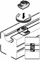 Tightening torque : 2.5 Nm (+/- 5%)

Frame
There is also that video I made of the second time I assembled the frame of my prototype. It shows the same thing, less optimized than the following illustrations, but may show you some tricks about how to use the T-nut : <videoflash>ohbzQX72Leo</videoflash>
Base Frame
- Foldarap frame base assembled.jpg
 x1
x1
 x1
x1
 x1
x1
 x1
x1
 x1
x1
 x1
x1
 x18
x18
 x18
x18
 x4
x4
 x4
x4


600px File:Foldarap frame base2.gif 600px
XZ Frame
- Foldarap frame XZ 9.jpg
(the x-end-idler may change slightly)
 x1
x1
 x1
x1
 x1
x1
 x1
x1
 x1
x1
 x1
x1
 x1
x1
 x1
x1
x2
x1
x1
x2
 x1
x1
x12
x12
 x2
x2
 x2
x2
600px
Hinge detail : 

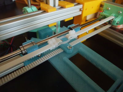
Y-Axis (105mm between smooth rods)
- Foldarap frame base assembled.jpg
check that the nuts can go inside their trap (the sides are open for a quick release of the bed without loosing the leveling (need test to confirm), while perfectly locked when tightened)
put the bearings in the y-plate, push the y-smooth-rods from one side of the machine, through the bearings and right to the other printed part (y-motor or idler regarding from wich side you pushed the rods). And check that everything slide freely :) (e.g. : http://www.flickr.com/photos/watsdesign/6988410463)
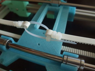
make a loop at each end of the belt with zip-ties (the orientation showed is the best I found), trim everything but keep a short length on the tensioning zip-tie to be able to pull on it with a plier.
after having tensioned the belt, slide the y-plate at the middle of the frame, align with the tensioning system and then clamp the belt (can be under or above the y-plate)
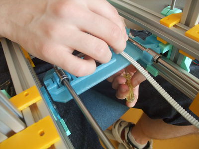
you also have to choose on wich side you like to have access to the bolts/nuts (under is almost always accessible)


Wiring
Motors
- Nema14
- For the geared stepper PG35L, after trying the three sequence (as suggested by StepperMotor#Shortcut_for_finding_the_proper_wiring_sequence), I found the order : Black (1B), Green (1A), Orange (2A), Yellow (2B).
Z-Axis (242mm between threaded rods)
- Foldarap frame base assembled.jpg
X-Axis (30mm between smooth rods)
- Foldarap frame base assembled.jpg
Extruder drive
- Foldarap frame base assembled.jpg
Printed Parts
Material
I'd recommend PLA over ABS, but it's maybe only required for the parts that act as sliders on the aluminium extrusions.
- x-end-motor_1off.stl
- x-end-idler_1off.stl
Recommended settings
For those who can print their own parts or want to replicate a FoldaRap :)
Nozzle diameter of reference : 0,5 mm


Skeinforge infill : 30-35% hexagonal for the big parts (as above left) ; or 20-25% of rectilinear (as above right) or hexagonal (or any dense pattern you like) infill with Slic3r.