Megatronics 2.0
Release status: Working
| Description | Single board solution, Remix of Arduino mega and RAMPS
|
| License | |
| Author | |
| Contributors | |
| Based-on | |
| Categories | |
| CAD Models | |
| External Link |
Contents
Summary
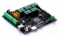
After using RAMPS for a long time I am still quite fond of it. There are some aspects of the board however that make it unusable for future electronics, which should be reliable and cheap. Also the wiring can we a bit fiddly. I have combined the Arduino MEGA and RAMPS boards into a single board solution. Only the stepper drivers are still modules for easy replacement.
Megatronics is based on many famous open-source products including: Arduino Mega 2560, RAMPS, SD Ramps. Therefor this product is an already proven design. It combines all major features of these board into a single board solution for more reliable 3D-printing.
Megatronics has a powerful Atmega2560 processor with 256 kB memory, running at 16Mhz. The board can be connected to a PC using a normal USB cable. It will register as FTDI FT232R device. The board is compatible with the Arduino Mega 2560 and will therefor be easily programmed from the Arduino IDE.
Testing the board
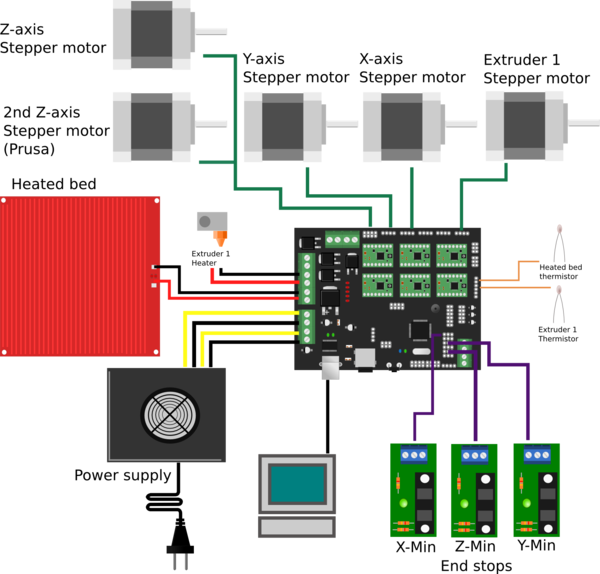
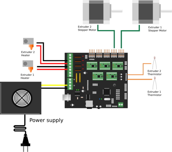
To test the functionality of the board, a test firmware is available. You can download it from the files section. This firmware will help you test the board. Disconnect everything except the USB cable to your computer. Upload the the test firmware to the board with Arduino, the blue debug LED should blink every second. By using the serial monitor in Arduino the board will provide an output like: T1 1023 T2 1023 T3 1023 TC1 700 TC2 700 These values represent the resistance measured from t1 to t3 and thermo couple 1 & 2. When you connect a thermistor to the pins, the corresponding value in the serial monitor should change to about 890.
By connecting the 12V lines, the MOSFETs should have power and their LEDs will blink in order. This verifies the MOSFETs and 12V power are OK.
Also the stepper motors should turn when connected, with the 12V lines and stepper drivers in place. They will turn a short time and switch direction.
These three tests will verify the basic functionality of the board.


