PortaPrusa Build Manual
|
English • العربية • български • català • čeština • Deutsch • Ελληνικά • español • فارسی • français • hrvatski • magyar • italiano • română • 日本語 • 한국어 • lietuvių • Nederlands • norsk • polski • português • русский • Türkçe • українська • 中文(中国大陆) • 中文(台灣) • עברית • azərbaycanca • |
Contents
About Build Manual
This is my personal build log, I will be posting regular updates as I make progress. Update: I just redesigned the printer, let's start over!
Still To Be Printed Parts
There are a few parts that I am considering making, such as pla bushings and a bar to lock the box open, but all existing files have been printed :)
Printed Parts
These are Completed Prints
| Quantity | STL file | Comments | Picture |
|---|---|---|---|
| 1 | X-Big.stl | Holds Motor | 
|
| 1 | X-Small.stl | 
| |
| 1 | Extruder.stl | 
| |
| 1 | Extruder-Arm.stl | 
| |
| 1 | Extruder-Plug.stl | Retaining plug for bearing | 
|
| 1 | Extruder-Clamp.stl | !!!Update File!!! | 
|
| 1 | Bed-Slide_Double.stl | 
| |
| 1 | Bed-Slide_Single.stl | 
| |
| 1 | Bed-BeltMount.stl | Top piece of belt clamp | 
|
| 1 | Bed-Clamp.stl | 
| |
| 2 | BasePivot.stl | 
| |
| 1 | BaseSlide_In.stl | 
| |
| 1 | BaseSlide_Out.stl | 
| |
| 2 | Drive-Gear.stl | 
| |
| 2 | Idle-Gear.stl | 
|
Laser Cut Parts
These Parts need to be laser cut.
- The Printer is made from '1/4 in' (.2 in) or 5mm sanded ply.
- You will need a 2ft x 3ft board to do it all. (usually sold in 4 ft sections)
The parts are contained in PortaPrusa_V3_Pack.dxf on the repo
Hardware
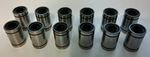
- Linear Bearings -
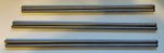
- Smooth Rod -

Electronics
Here are some of the electronics I'm using.
- Extruder -
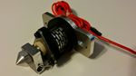 I'm not sure what this extruder is called, will try to update when I figure that out.
 - Controller -
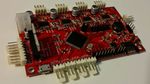 This printrboard was made by geeetech, I got it on sale for a great price! :)
 - Motors -
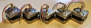 I'm using 5 compact Nema 17 stepper motors. Most Nema17s are pretty similar, but there are some differences, mainly in the wires.


==Building Guide== Ignore - out of date
Step One
The first thing you need to do is insert the linear bearings into their respective 3d parts.

Step Two
We will now mount the Z-motors to their mounts, and attach those to the frame.
Vitamins - 3x M3 bolts, nuts
Note - my motors came with bolts, yours may not.
![]()

Step Three
It's time to assemble the X carriage.
Note - I had to drill out some holes for the smooth rods to fit.
![]()
Step Four
Now we will put together the sliding mechanism.
Vitamins - 8x M3 bolts, nuts; a couple bolts and washers for pivots.
