ITopie Build Manual
This page is a development stub. Please enhance this page by adding information, cad files, nice big images, and well structured data!
|
English • العربية • български • català • čeština • Deutsch • Ελληνικά • español • فارسی • français • hrvatski • magyar • italiano • română • 日本語 • 한국어 • lietuvių • Nederlands • norsk • polski • português • русский • Türkçe • українська • 中文(中国大陆) • 中文(台灣) • עברית • azərbaycanca • |
Get the sources
The first thing you need is a local copy of the source files (OpenSCAD, DXF, STL, etc...).
The simple way to get it is to download/clone the git repository at https://github.com/lautr3k/RepRap-iTopie.
git clone https://github.com/lautr3k/RepRap-iTopie.git
or
wget https://github.com/lautr3k/RepRap-iTopie/archive/dev.zip
Make the default frame
If you do not want a customized version, you can simply use the generated DXF files in the ./build/output directory for milling/cutting your frame.
CNC milling version
./build/output/iTopie_plates-CNC-16mm_thickness.dxf
Laser cut version (experimental)
./build/output/iTopie_plates-LaserCut-16mm_thickness.dxf
Make an custom frame
Configuration
If you want a custom frame, you need OpenSCAD to edit and parse/compile the scad source files.
After installing OpenSCAD, open it and select "Design->Automatic Reload and Compile" and "View->Hide editor".
Now you can open the ./scad/main.scad file for an live preview of all change made in the configuration file.
And then open the ./scad/config.scad in your favorite text/code editor to made change.
(Whenever the file is saved to disk (from within the external editor), OpenSCAD will recognize the file change and automatically recompiles accordingly.)
DXF files builder
The recomended way is to use the python script in the ./build directory. It will generate for you a single cleaned DXF file with layers, depending on your scad configuration file.
Usage
usage: build.py [-h] [--target int] [--output_type int] [--output_dir path]
                [--output_file filename] [--output_clean] [--tmp_dir path]
                [--tmp_clean] [--odmt path] [--scad path] [--openscad path]
                [--clean] [--version]
Options
optional arguments:
  -h, --help            show this help message and exit
  --target int
                        output version (default : 0)
                        ----------------------------
                        0 : CNC milling (default)
                        1 : Laser cutting
  --output_type int, -t int
                        output type (default : 0)
                        -------------------------
                        0 : all (plate 1 and plate 2 in one file)
                        1 : plate 1 (horizontal_plate, y_carriage, feet)
                        2 : plate 2 (vertical_plate, triangles, feet)
  --output_dir path, -d path
                        path to the output directory (default : ./output)
  --output_file filename, -f filename
                        output filename without extension (default : auto)
  --output_clean        remove all files in the output directory (default : false)
  --tmp_dir path        path to the temporary directory (default : ./tmp)
  --tmp_clean           remove all files in the temporary directory (default : true)
  --odmt path           path to the OpenSCAD DXF Merge Tool (default : ../odmt/odmt.py)
  --scad path           path to the main OpenSCAD file (default : ../scad/main.scad)
  --openscad path       path to the OpenSCAD binary (default : C:/Program Files/OpenSCAD/openscad.exe)
  --clean, -c           remove all files in temporary and output directories (default : false)
  --version, -v         show program's version number and exit
Examples
python build.py -f iTopie_plates-CNC-16mm_thickness
Produces iTopie_plates-CNC-16mm_thickness.dxf in the defaut ./build/output directory.

Build manual
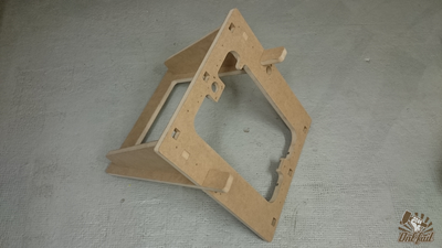
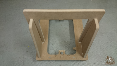
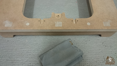
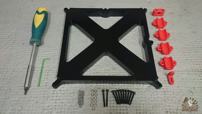
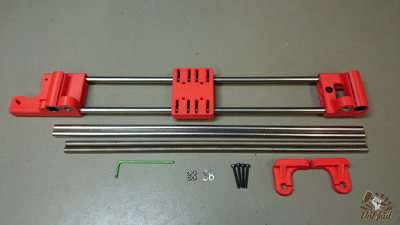
Frame assembly
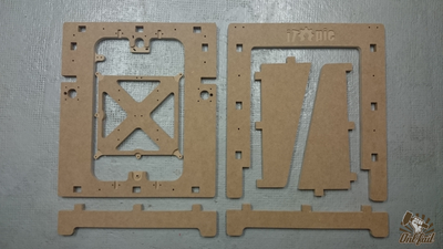
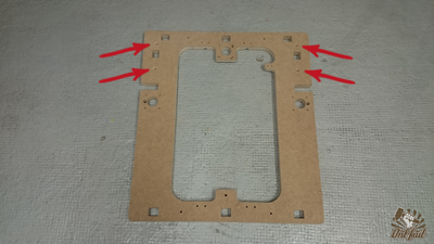
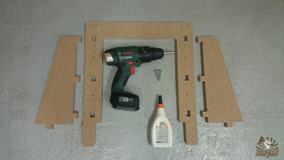
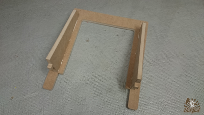
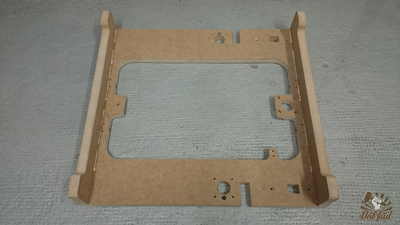
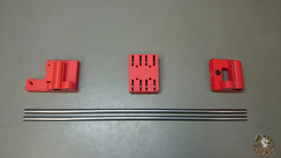
All frame parts you need.
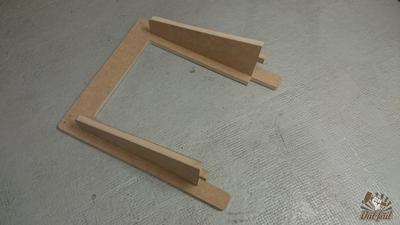
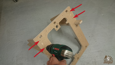
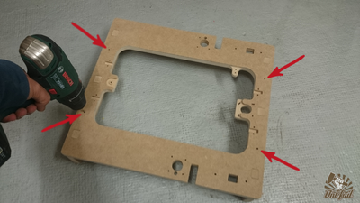
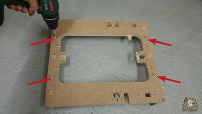
Fit the rears triangles on the "U" part.
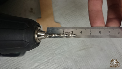
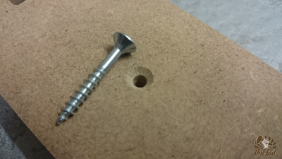
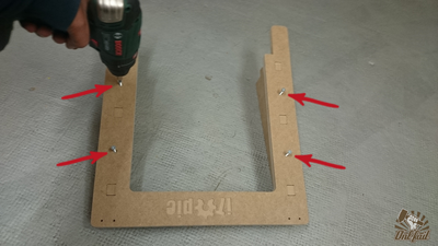
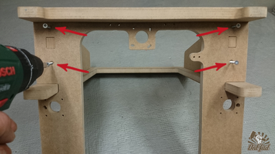
Take a 3mm drillbit and adjuste to 3.5cm from the mandrel.
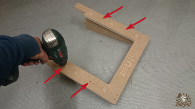
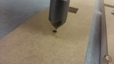
Make some holes. (4x)
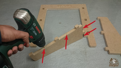
Fit the assembly on the "O" part.
Make more holes. (4x)
Remove all parts and remake again the holes in depth. (8x)
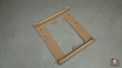
Ok !, Fit the feet on the "O" part.
Turn back and... yes ! more and more holes. (4x)
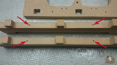
Same as above, unplug the parts and remake the holes. (4x)
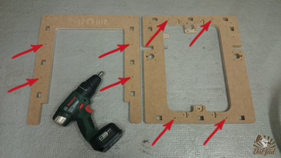
The chamfers, optional but recommended.
"O" part back side chamfers positions.
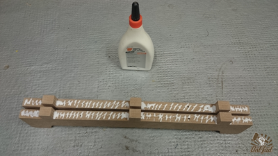
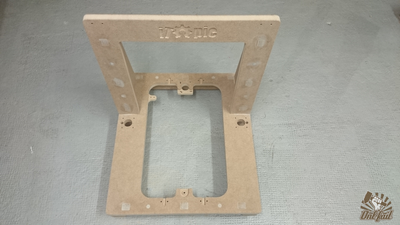
Glue and screws party.
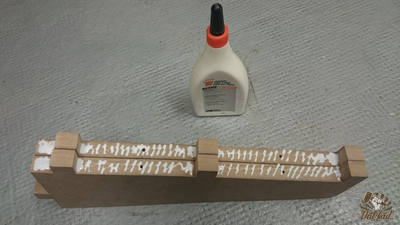
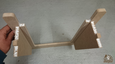
Apply some glue on the two triangle.
Re-Fit the rear triangle on the "U" part and press hard.
Turn back and screw all together wite four 3.5x40mm screws.
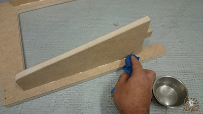
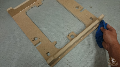
With a wet cloth, wipe the superfluous glue.
Take the feet and apply some glue.
Plug the feet and press hard.
Turn back and screw all together wite four 3.5x40mm screws.
As before, clean the glue.
Apply some glue as pictured.
Fit all together and press hard.
Turn back and screw all together wite four 3.5x40mm screws.
Do not forget to clean the glue.


At this point your frame is finished and functional. The following statement is optional but highly recommended.
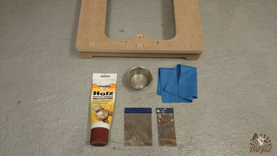
Frame puttying, sanding, painting and lacquering
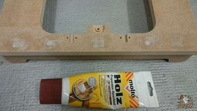
Apply some wood putty, over screws head and frame connectors.
When the putty is dry, sand superfluous.
Clean dust from sanding.
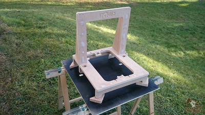
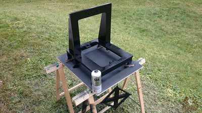
Find a good place for painting.
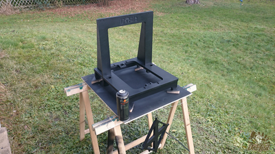
Apply color (two coats).
Apply the lacquer (two coats).
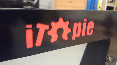
Glue the printed iTopie logo.
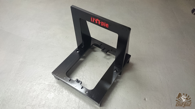
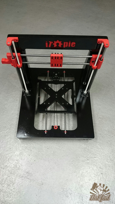
Frame assembly done!


X Axis (1/2)
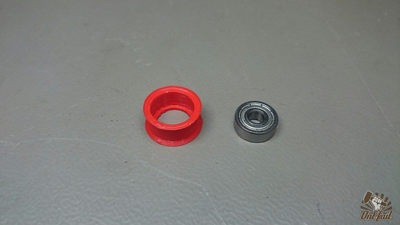
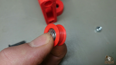
Take one 605(z) bearing and the printed flange.
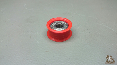
Insert the 605(z) bearing in the printed flange.

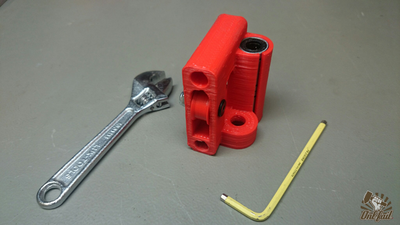
Take the x-end (idler side) and two LM8UU bearing.
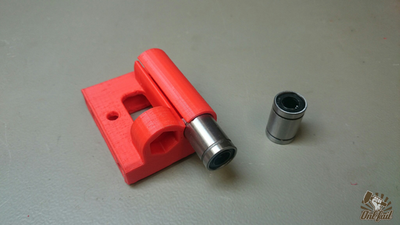
Push the two bearing in the x-end.
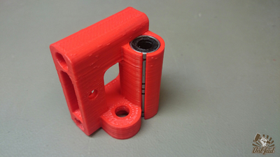
Once is done.
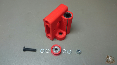
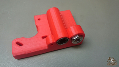
Take one M5x20mm screw, four washers of 1mm thick and one M5 nylock nut.
Put two washers one each side of the idler bearing.
Slid the bearing in the x-end, and lock wite the screw/nut.
Push one M8 nut on each x-end.
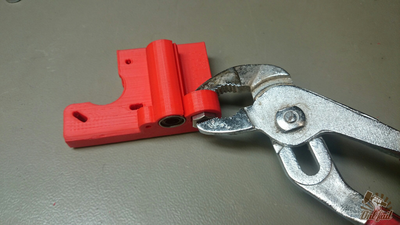
If needed, use a pliers.
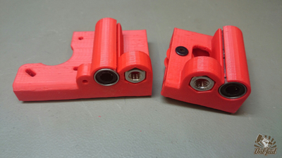
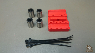
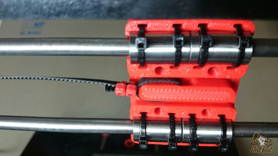
Take four LM8UU, eight zip ties and the x-carriage.
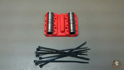
Push the four LM8UU on the x-carriage.
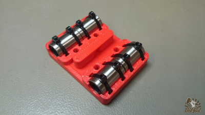
Secure with zip ties.
Take the two x-end, and the two 380mm smooth rods.
Insert the two rods in one x-end.
Slide the x-carriage and clip the other x-end to complete.


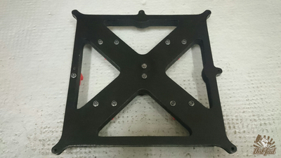
Y Axis
11 x M3 nuts
12 x M3 washers (do not rely on the image)
11 x M3 x 30mm screws (do not rely on the image)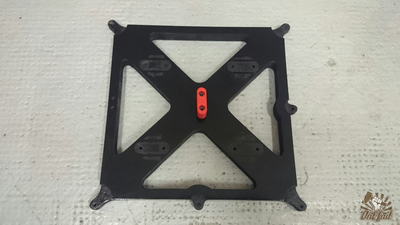
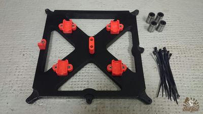
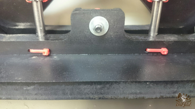
Securely tighten the belt holder with two screws (washers and nuts) in the center of the y-carriage.
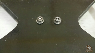
Do not forget to add a washer on each screw.
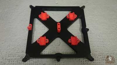
Loosely tighten the four LM8UU holders with two screws (washers and nuts) on each. We must tighten thoroughly later.
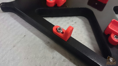
Attach the flag of the limit with a washer on each side.
Pay attention to the orientation of the plate and the flag.
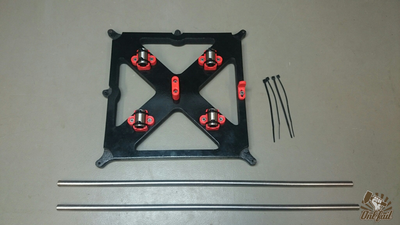
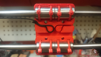
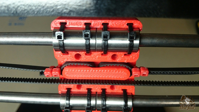
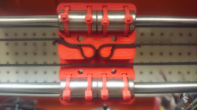
4 x LM8UU
8 x zip ties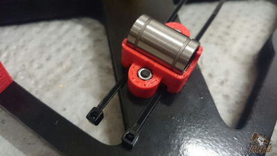
Firmly press the bearing in the holder and tighten the zip ties thoroughly.
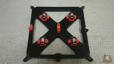
The same with the others.
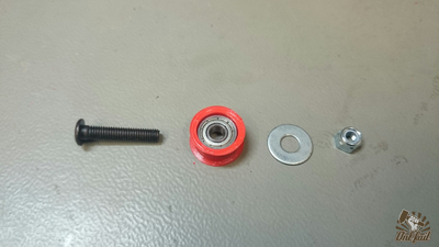
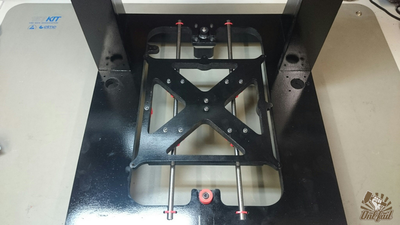
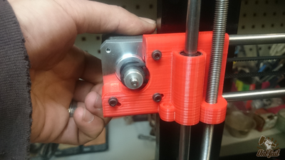
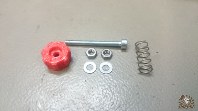
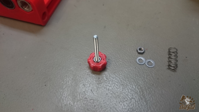
1 x M5 x 25mm
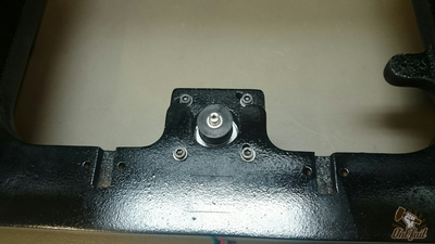
1 x 605(z) bearing
1 x printed flange
1 x M5 washer
1 x M5 nylock nut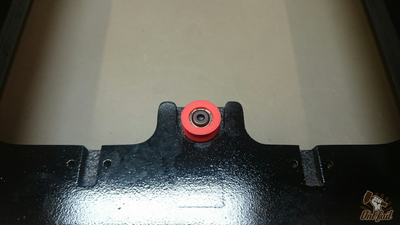
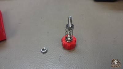
Place the flanged bearing in place and insert the screw.
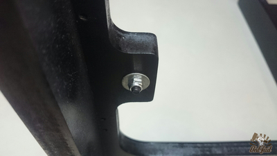
Add on other side the washer and nut and tighten firmly.
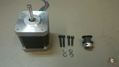
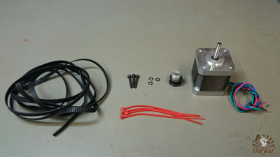
1 x Nema 17 motor
4 x M3 washers
2 x M3 x 22mm screws
2 x M3 x 16mm screws
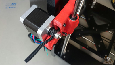
1 x toothed pulley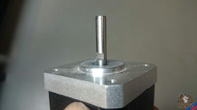
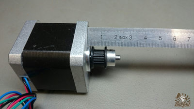
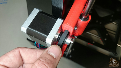
Make a groove on the shaft of the motor for a good tightening of the pulley.
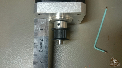
Adjust the pulley, the belt must be positioned between one and two centimeters from the base of motor.
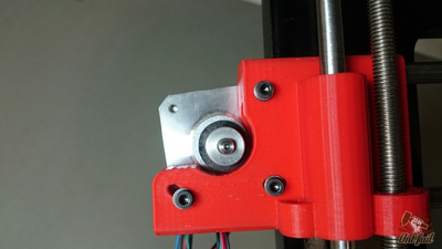
Secure the motor to hold it in place. Do not overtighten.
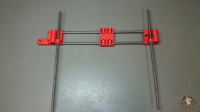
2 x 400mm smooth rods
8 x zip ties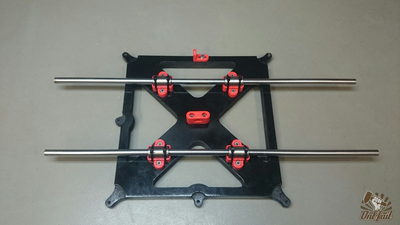
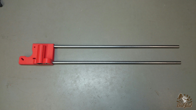
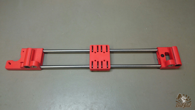
Slide the two smooth rods.
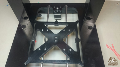
Clip the assembly in the frame.
Secure the bar with the zip ties.
It's time to tighten the four LM8UU holders of the y-carriage. Check that the carriage moves properly between each clamping.
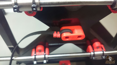
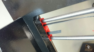
Attach the 800mm GT2 belt with two zip ties on is holder at the center of the carriage.
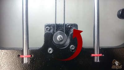
Pass the belt around the motor pulley. Make sure the engine is released (turn left).
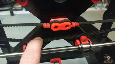
Pass the belt around the idler pulley and tie it back to the center.
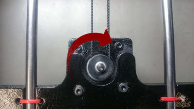
To tighten the belt turn the motor clockwise and tighten.
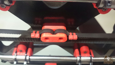
The belt is tight and the Y axis is done.


Z Axis
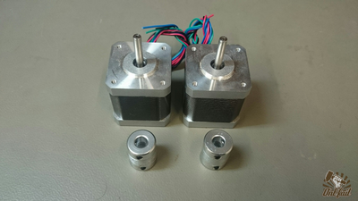
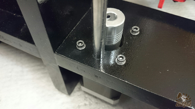
Take two nema 17 motor and two coupler. Fix the two coupler on the shaft of the motor.
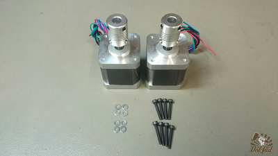
8 x M3 x 20mm screws
8 x M3 washers
Firmly secure the two motor on the frame.
1 x X-axis assembly
2 x 380mm smooth rods
2 x 360mm threaded rods
4 x M3 x 25mm screws
4 x M3 washers
4 x M3 nuts
2 x Z rod holder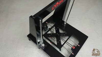
Clip the two smooth rods in the frame.
Make sure it is fully inserted, use a hammer if necessary.
Screw the two threaded rods in the assembly.
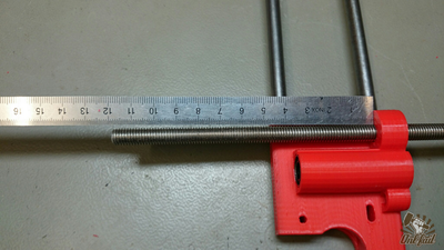
Screw around 10/15 cm from the top.
Slide the assembly on the smooth rods and guid the threaded rods into the couplers.
Firmly tighten the couplers.
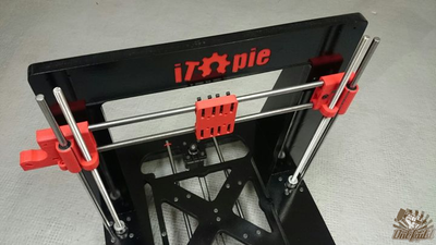
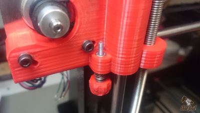
Insert the two top bracket on the smooth rods.
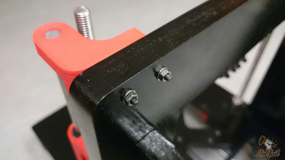
Adjust the brackets and secure them to the frame with two M3 x 20mm screws.
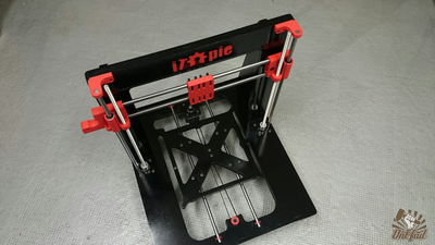
Z axis is done!


X axis (2/2)
...
...
...
...
x-carriage v2
...
...
...
...
x-carriage v2
...

...


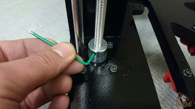
Endstops
X axis
Y axis
Z axis
...
...
...
...


