RepRapMicron
This page is a development stub. Please enhance this page by adding information, cad files, nice big images, and well structured data!
//identifies pages under construction. remove when the page is relatively stable.
Release status: Early development
| Description | Micron-scale 3D Printer
|
| License | |
| Author | |
| Contributors | |
| Based-on | |
| Categories | |
| CAD Models | |
| External Link |
Contents
Summary
The µRepRap is intended to be a RepRap capable of micron (1/1000th of a millimetre, or 1µm) and sub-micron fabrication. This degree of accuracy has been made possible by 3D printed microscope platforms designed by The OpenFlexure Project. Expectations for the initial prototype are to demonstrate repeatable positioning to better than 3µm on a work area 10mm across, and to produce a probe tip in lieu of a print head that is suitable for manufacture in a simple home workshop.
Overview
Microelectronics and Micro-electromechanical Systems (MEMS) are essential components of most of the electronic wizardry we use in our everyday lives, whether we realise it or not. In the way that RepRap brought Open 3D fabrication to the masses, the aim of the µRepRap Project is to bring users the same capabilities on a much smaller scale and allow those components to evolve in the same way.
Background
Precision manufacturing began somewhere in the 1700's, and the first micron scale electronic devices were fabricated from silicon in the 1960’s. Ever since then the technology focused largely on silicon, with fabrication systems becoming ever more complex, esoteric, and costly. The techniques used are difficult for the average hobbyist to manage, and in many cases are downright dangerous.
In biology and medicine, equipment to measure and manipulate objects on the micron scale are relatively common - though these devices tend to be large, specialized, and expensive. Recently though, microscope platforms capable of sub-micron resolution were developed by The OpenFlexure Project, and these have created an opportunity for developing micron scale fabrication.
If micron scale manufacturing can be achieved by RepRap-like technology, it is likely that these fields will be advanced in the same way that manufacturing was by the RepRap. The biological sciences will gain from inexpensive, rapidly-evolving equipment. The microelectronics field will regain the potential for independent communities develop on the micron scale, and break away from its fixation on silicon as its main platform. As with 3D printing, there will certainly be new developments in fields that do not currently even exist.
There is the interesting possibility that this technology could replicate, and even do so at a yet smaller scale.
Requirements
Micron scale 3D printing has many of the same requirements that The RepRap Project developed when initially printing on the macro scale:
- A 3-axis positioning system
- CAD/CAM software
- Axis zeroing sensors
- A deposition system
- Building material
In addition there is the practical aspect that humans are unable to directly manipulate micron scale assemblies and sub-assemblies. Novel systems are therefore needed to:
- Detach printed items
- Transport items
- Rotate and position items
- Conduct micron scale maintenance tasks
While conventional optics are readily available to allow humans to initiate and inspect the fabrication processes, it is likely that some customisation of the optics will be desirable.
Adaption Of Existing RepRap Technology
The 3-axis positioning systems developed for the RepRap are largely applicable to operation on the micron scale. They are also readily available and understood by many potential collaborators. Likewise the CAD/CAM systems developed can largely describe the volumetric and control aspects on the micron scale. Early RepRap designs catered for many initial design issues experienced, such as backlash and the management of delays in the extrusion system, and these will likely have parallels.
One example would be the positioning system. Current 3D printers use microswitches, optoelectronics, and hall-effect sensors to detect the zero position of an axis. Others simply slam the axis into a physical stop. One possible solution is a light gate closing off a light source, the light minima indicating a known position. Actual probe height above the work area needs to be determined, and this initially is likely to be a manual process.
The control of the deposition process and the choice of building material will need to be reconsidered due to the practical issues of creating fine extrusion orifices and moving phase-changing materials through them. Photosensitive resins as used in resin printers do scale however, and similar materials are already used widely in the microelectronics industry. Their wide availability to the 3D printing community makes them worthy of consideration. If the work area is illuminated by UV for photosetting from underneath, the reservoir of resin can be kept in a shielded portion of the work area above. The probe can shelter in this area when exposure is in progress, and reload itself with resin at the same time.
It is likely that a number of substances with desirable physical properties will be experimented with. Conductive and electrically active materials are an obvious step. A magnetic material would allow a means of activating assemblies by means of an external magnetic field. Droplets of catalyst could be used to solidify a substrate or render it soluble etc.
Novel Requirements
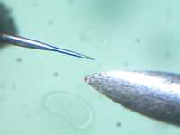
The simplest form of deposition system is an old-fashioned dip pen. It requires no more than being dipped in an inkwell, and then to be touched to a surface. If the ink can be persuaded to change phase by thermal cycling, photosetting, or application of electricity etc., the print head itself need not have any complex or moving parts.A sufficiently sharp tip, in the sub-micron range, can be easily made on the workbench from fine wire. 22 gauge (0.12mm) titanium or nichrome wire work well. Place a large electrode in the bottom of a container of 5% sodium chloride solution and connect this to the negative side of 3 AA cells in series. Suspend a length of wire vertically in the salt solution, and apply +4.5V to it. Electrochemical erosion occurs, and when the end of the wire falls of, cut the current. The process takes a few minutes and can be automated or done manually.
Combined, these items allow the formation of a test system for deposition, operated by conventional CAD/CAM systems attached to an OpenFlexure stage.
Assembly Manipulation
Seeing the object being fabricated during development is crucial. As micron scale optics tend to be very 2D and have a limited depth of focus, gauging the height of things is particularly difficult. There are some tricks that can be applied such as creating shadows, and illuminating the object with different coloured LEDs from several angles. These techniques are also useful for observing completed objects.
Once an object has been fabricated, one way to detach and manoeuvre it would be to simply use the “ink” to glue the probe tip to the assembly. While adequate for initial experimentation, eventual re-use of the probe is desirable and a release mechanism such as heating the probe tip could be implemented.
To rotate parts does not necessarily require a rotating manipulator. Parts could be made to rotate around built-in pivots when moved or operated with the probe. To move in the vertical plane, an assembly could contain joints that allow it to erect itself at the desired angle by manipulation of hold points with the probe. Once the assembly is in the required orientation the probe can be glued to the angled assembly. By use of multiple probes, each attached to an OpenFlexure stage, and the ability to apply glue, assemblies can be combined arbitrarily to produce macro-scale items and either positioned with the probe or more conventional manipulation. Another possibility is electroadhesion or plain old magnetism, but this only works with some materials.
The maintenance tasks are currently unknown. Likely more convenient tools – grippers, rotating devices, probe recovery systems, ink well fillers – will need to be manufactured. The early stage of development will likely have a high attrition rate.
Future Advances
As with the original RepRap, it is hoped that once the first μRepRap is operational, it will be able to replicate. Unlike the original, the replicant will not be identical to its parent but will be a much smaller functional equivalent. Control of the replicant will be difficult, but not impractical. Options include perpendicular magnetic fields, inducing vibrations to operate ratchet mechanisms or tuned structures, or at its most basic cranking the mechanism with the tip of a probe until something better can be worked out. It should be possible to run more than one printing mechanism simultaneously.
It might also be possible to fabricate a μRepRap that is scaled down further. Assume that a RepRap has a precision of approximately 0.2mm on a 200x200mm work area, and a μRepRap has approximately 1 micron resolution on a 10x10mm work area. We see roughly two to three magnitudes in reduction in scale. If flexure systems also scale, then it might be possible to use a μRepRap to create a smaller printer with a resolution on the nanometre scale. Unlike current attempts to operate with nanometre precision with macro scale hardware, errors in the device due to thermal expansion and other material-related noise would be much reduced. It would at least be interesting to see how far this limit could be pushed.
Practical Progress
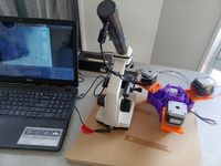
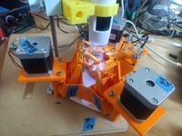
To commence experimentation an OpenFlexure Delta Stage was constructed with two modifications: A simple beam extension (two 85mm lengths of No. 12 fencing wire soldered at an angle for bracing) to allow the probe to be moved in the field of view of a conventional microscope capable of sub-micron resolution, and the driving of a single axis of the stage with a NEMA17 stepper motor. By controlling the stepper with a standard RAMPS board and 3D printer software, a repeatable motion with a step accuracy of approximately 3 microns was observed. Model files required can be found at https://www.printables.com/model/797699
Probe tips were held in standard hypodermic needles bent aprox. 4mm from the tip at aprox 80 degrees. A croc clip fits in the cavity in the needle base, and allowed replacement and positioning in the early experiments. Hypodermic needles themselves are reasonably robust substitutes for delicate probes, and the author plans to make a variety of tips.
As the Marlin 3D printer software is theoretically capable of operating a delta stage, though configuration was problematic and the OpenFlexure stage is not a traditional RepRap delta configuration. The solution was to replace the Marlin delta firmware with standard GRBL-servo XYZ-axis software and use a portable Python program to implement the kinematics and a control panel. This is expected to provide an experimental platform capable of reliably moving a probe in 3 dimensions under the view of a suitable microscope. Assistance with porting the model to Marlin or any other RepRap firmware would be appreciated, as this is a more flexible solution long-term.
Subsequently a second experimental platform was built based on the OpenFlexure indirect lighting stage. This allowed a more robust and adjustable probe holder to be fitted to the lighting stage. The same upgrade added microswitches to the delta stage feet to facilitate automatic levelling in GRBL.
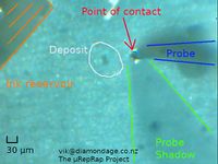
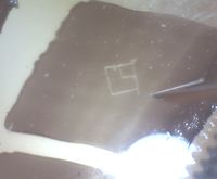
Initial tests showed the probe can make marks in a coloured substrate (Sharpie marker on a microscope slide) and deposit controlled dots and streaks of a viscous fluid (motor oil with soot mixed in) at intervals on the slide. Later tests showed good alignment for 0.1mm squares arranged in a cross, and the Sharpie is starting to tear unpredictably losing edge definition with lines thinner than 10μm. Initial tests show deposited dots correspond closely to the tip size, and that multiple dots can be created with one dip of the probe in the fluid. XY movement is reasonably well controlled, and effort is being put in to automate movement using gcode files. Once this is well tested, an attempt will be made to deposit UV-sensitive photopolymer resins, cure them, and progress to multiple layers.
Some changes will be needed to the Delta Stage and Software. The Delta Stage is primarily intended as a finished article for microscopy, and we're after something that can be hacked about a bit. The GRBL software will need to control the deposition system, and probably illumination (though as mentioned earlier would ideally be replaced).
Cats
Cat hair varies between species, but Ragdoll hair has a diameter of around 30μm. If you have a cat, it is strongly advised that you keep them off the workbench or you too will be observing the diameter of cat hairs.
Collaboration
The project will be conducted as Open Source under the terms of the GPL 3 or later licence where possible, and documentation distributed under the terms of the GFDL. Progress will be blogged on the reprap.org blog, and the primary repository for technical details and conclusions will be on the reprap.org wiki. Software and configuration files are on GitHub. Participation is encouraged. There is likely to be some discussion on the Facebook RepRap page - note that due to spam you must answer the group question before posting on Facebook!
As a side note, the original Z80 processor was manufactured using an 8 micron process. Construction of assemblies on this scale seems an achievable goal.
Conclusion
Hopefully this will bring the RepRap project to smaller and smaller things. VikOlliver (talk) 22:44, 6 March 2024 (EST)

