MM PLD - v0
Release status: Abandoned
| Description | First iteration of the MM_PLD, based of an existing system
|
| License | GPL
|
| Author | |
| Contributors | |
| Based-on | [[]]
|
| Categories | |
| CAD Models | |
| External Link |
Contents
Multi Material Pulsed Laser Deposition
Vacuum Chamber
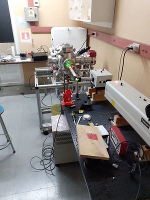
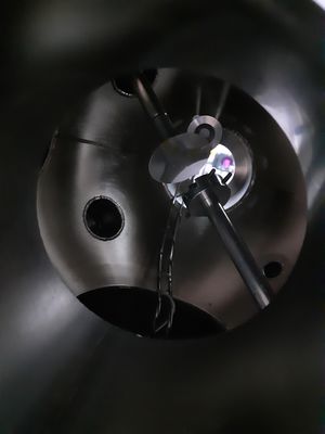
So when I began working with the deposition system, it had a quite standard configuration. Most of the design choices were already made, and I only had to design and fabricate the in-chamber mechanical components. The system had a MDC spherical vacuum chamber with plenty CF flanges emerging radially at different angles. The target and substrate were diametrically opposed, as can be seen in the following picture.
It held a 25mm target rotating at about 20 rpm at a distance which could be adjusted between 50 and 70 mm by a translation/rotation manipulator located in the substrate flange.
The system used a QCM to monitor the thickness of the films.
Laser and Optics
Ablation was achieved by means of a frequency doubled Nd-YAG laser (Continuum) which was capable of producing 30 ns pulses of about 300mJ total energy, with a repetition rate of up to 10Hz. The beam was filtered by an dichroic mirror, and steered by other mirror towards a lens which focused the light onto the target.
The Multi Target Flange
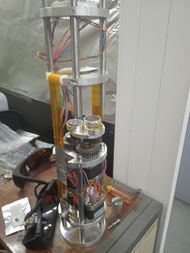
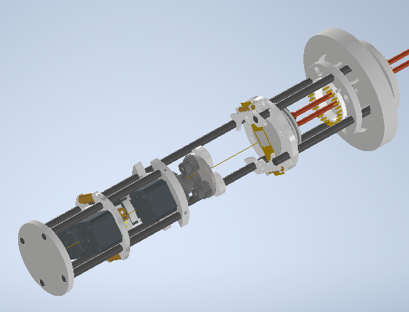
Now the relatively 'novel' part is on the in-chamber configuration. I had to be able to move the target carousel, have each of the targets rotate continuously around it's normal axis, and move the tape to change the masks. While one could have gotten away with 3 DoF, I liked the idea of being able to move the tape back and forth in order to make [Dynamic shadow masking] a possibility. An due to the need to adjust precisely the tape position on the transverse direction, I ended up with six actuators. Since it was impossible (and would have been ridiculously expensive) to accommodate all of them on flanges with motion feedthroughs, I chose to use vacuum rated stepper motors and piezo actuators which were assembled onto a kind of 'capsule' that one could easily remove from the camber. The electrical connections were achieved by an array of 2.5 mm banana connectors at the top.
Here`s a short description of all the components:
Target Carousel
A quite relevant requirement for standard PLD systems is that the ablation spot should move relative to the target surface, in order to avoid creating a 'pit' which could lead to temporal variation of the plume profile and composition. The usual solution is to make the target rotate on it's own axis, generating a circular path.
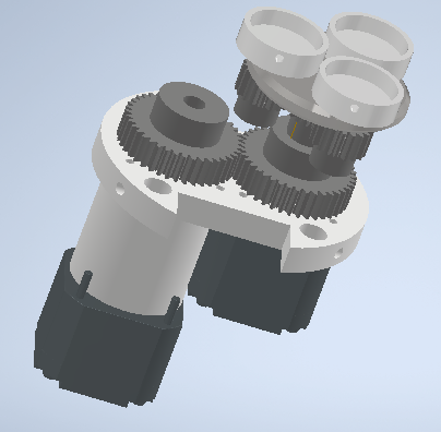
The designed target carousel uses two stepper motors: one directly coupled to the carousel to select the target being ablated at any given moment, and another which turned a gear system which ensure the target's rotation. The design is quite standard, and is inspired by this publication.
The cylinder is a spacer for mounting the motors. The original design was intended for NEMA14 motors, but while trying to vacuum-proof standar motors I became worried about the required torque, so when ordering the actual motors I played it safe and went with NEMA17, which did not fit that well.
The carousel holds three 25mm targets.
Tape Mechanism
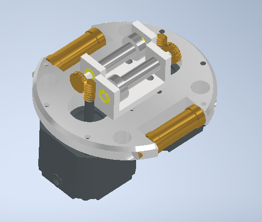
Each stepper motor drives a worm wear which turns each roll.
Tape Fabrication
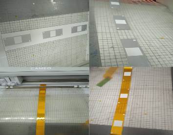
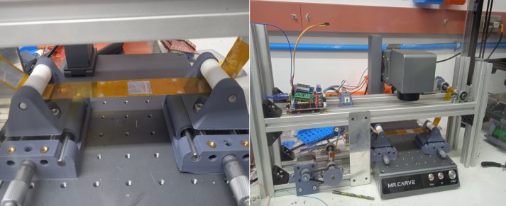
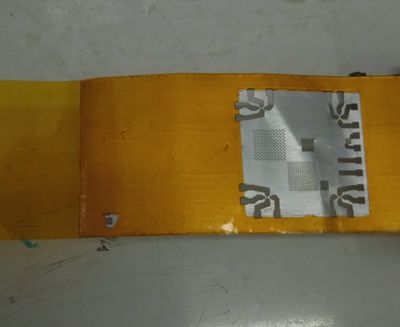
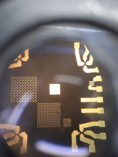
The tape was first intended to be made out of polyimide due to it's appropiate mechanical and thermal properties, but after the first prototypes apertures didn't hold the expected tolerances. Therefore, I decided that a small 20mm*20mm region made of 30 micrometers thick aluminum tape would actually hold the apertures and aligning masks, which performed way better when laser cut. A vinyl cutter was used to generate the desired 'blank' tape.
Then, the tape was rolled and fed onto a custom rig which dealt with positioning, while a fiber laser cutter [[1]] was used to machine the apertures. While according to the manufacturer it had a positioning repeatability and accuracy of about 1 micrometer, the critical feature size was actually about 20 times that, mainly due to the high aspect ratio of the holes.
Mask Aligner
An extremely important consideration if we aim to make devices and heterostructures which actually work is to control the registration between each successive layer, which basically means that there are no displacements of a magnitude of perhaps a fraction of the minimal feature size between each mask.
As you may see from the tape fabrication process, I didn't though that the mechanism alone could be trusted with such degree of repeatability. Thus, a mask alignment scheme was implemented.
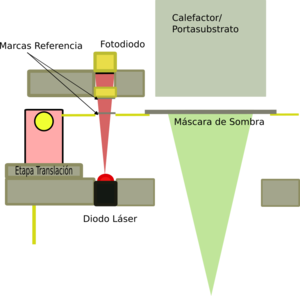
The idea is that along with the apertures that define the mask, one could generate a set of alignment marks some distance away from the place where the substrate should be during deposition. Then, if we make an exact copy of such pattern which is fixed to the frame of the machine and shine a light through both of them, the intensity maximum should be when both mask are in perfect registration.
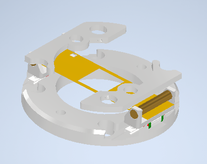
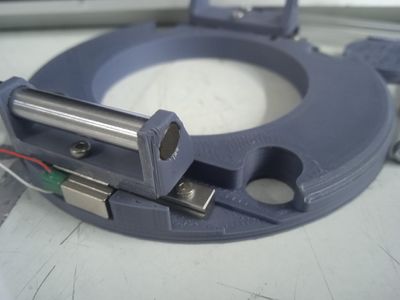
Now tape actuation in the longitudinal direction was taken care by the tape mechanism, but transverse displacement and rotations needed to be taken care also. Since there wasn't much space available, I used a couple off piezoelectric actuators magnetically coupled to a linear guide. The idea came from [this excellent paper]
The magnetic coupling is a more practical implementation of whats known as an inertial actuator, where one may perform either short range, high resolution motion or larger steps according to the signal fed to the piezos.
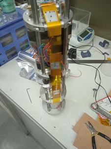
Here is a prototype of the actuator:
