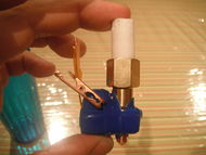
Wildseyed Simple Hot End
Release status: Working
| Description | Wildseyed Simple Hot End
|
| License | GPL
|
| Author | |
| Contributors | |
| Based-on | [[]]
|
| Categories | |
| CAD Models | |
| External Link |
Design Goals
- Simple construction with readily available tools and materials
- Reliability
- Easy Removal
- Low Cost
Tools Required
- Drill Press
- Drill Bits
- Hack Saw
- Tap and Die Set
- Large Pliers or Vice Grips
- Flat File
- Caliper
- Scissors
- Soldering Iron
- Barrel Crimp Tool
- Small Brush or Cotton Swab
Materials Required
- Aluminum Block - 1" x 1/2" x 1/2" (LxWxH)
- Brass Coupling - Air Hose Type Female 1/4"
- Copper MIG Type Welder Tip - 0.025/0.6mm
- Set Screws - M4x5mm(1), M4x10mm(4)
- PTFE Rod - 1.5" x 1/2" (L x D)
- Thermistor - 100k, Glass Bead
- Power Resistor - Aluminum Encased, Dale 5 Ohm 1% 5 Watt
- Kapton Tape
- Emergency Tape
- Heat Sink Compound
- Crimp-on barrel connectors - Small
- Small Alligator clips
- Insulated Wire - Teflon preffered, but any will do
- Plastic Ties
Assembly in Seven Easy Steps
- The Aluminum Block
- The Brass Coupling
- The MIG Welder Tip
- The PTFE Rod
- The Thermistor
- The Power Resistor
- The Wraps
Step One - The Aluminum Block
200px|thumb|left|The Aluminum Block When drilling the aluminum block on a drill press, holding the block using pliers eliminates troublesome vibrations.
Using a punch, and a 7/16" bit, drill a hole through all, from the top of the aluminum block. The hole should be equi-distant from the three nearest edges. For example, if the block's top dimensions are 1" x 1/2", the the hole should be centered at 1/4" x 1/4".
Next, widen the top half of the 7/16" hole using a 1/4" bit.
Finally, use a M3.5 bit to drill a hole for the set screw. Tap it with a M4 bit.
Step Two - The Brass Coupling
in progress...
Step Three - The MIG Welder Tip
in progress...
Step Four - The PTFE Rod
in progress...
Step Five - The Thermistor
The thermistor is the most likely cause of failure in any hot end. It is very fragile, and subject to shorts if not installed properly. Careful installation will ensure reliable operation, and accurate temperature measurements.
For this step, you will need a 100k Thermistor, and several lengths of Kapton tape. The goal is to encase the thermistor in several layers of capton tape, to insure that the leeds are insulated and supported, while still exposing as much of the glass bead as possible to direct contact with the heated surface.
Step Six - The Power Resistor
in progress...
Step Seven - The Wrap
in progress...
