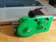
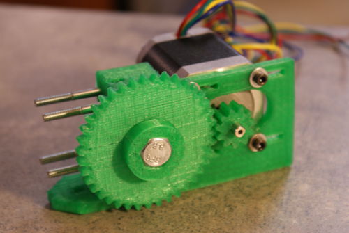
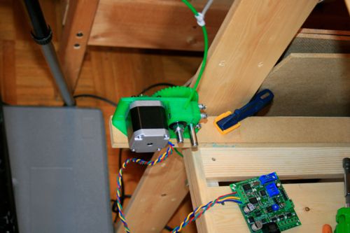
Wade's Geared Extruder/pt
|
English • العربية • български • català • čeština • Deutsch • Ελληνικά • español • فارسی • français • hrvatski • magyar • italiano • română • 日本語 • 한국어 • lietuvių • Nederlands • norsk • polski • português • русский • Türkçe • українська • 中文(中国大陆) • 中文(台灣) • עברית • azərbaycanca • |
Release status: Working
| Description | Geared Nema 17 Extruder
|
| License | GPL
|
| Author | |
| Contributors | |
| Based-on | |
| Categories | |
| CAD Models | |
| External Link |
Funciona com extrusor Adrian's Geared para Nema 14(Adrian's Geared Extruder), inclui muitos conceitos levantados a partir de estudos da extrusora de Nophead (Nophead's Extruder Tweaks).
Esta extrusora foi projetada para a RepRap Sells Mendel (mas pode trabalhar com qualquer impressora 3D, basta adaptar) e é robusto, proporciona uma grande força para extrudir, é barato e “faça você mesmo”. É uma alternativa ao Geared Nema17 Extruder Driver e tem as seguintes vantagens:
- não há necessidade de comprar / usar engrenagens de metal caras;
- não há necessidade de fazer dois cortes de precisão sobre o eixo do motor;
- não há necessidade de colar o barril PTFE;
Outras vantagens sobre outras extrusoras são:
- extrusão / impressão em alta velocidade;
- bom para uso com um torque de baixo / barato motor Nema 17; (Precisa de verificação)
- não há necessidade de usar ferramentas caras e complexas - apenas uma broca de mão, um arquivo e um torno M4 ou M5.
- não há necessidade de fazer estrias no eixo do motor;
Contents
Como obter
Este projeto é feito com foco faça você mesmo, caso não consiga fazer o seu, ou simplesmente não queira faze-lo, você pode sempre comprar um. Muitos usuários imprimem suas peças e vendem no e-bay, no mercado livre, e outras lojas podem ser achadas no google, busque por Wade's Geared Extruder.
Montagem
Materiais
Partes Impressas
| Quantity | Description | Type | Comments | Diagram |
|---|---|---|---|---|
| 1 | extruder block | RP | File:M8 Extruder 3.zip | |
| 1 | extruder idler block | RP | File:M8 Extruder 3.zip | |
| 1 | 11 tooth drive gear | RP | File:M8 Gears.zip | |
| 1 | 39 tooth M8 hub driven gear | RP | File:M8 Gears.zip | 
|
Partes não Impressas
| Quantia | Modelo | Tipo | Descrição |
|---|---|---|---|
| Alimentador | |||
| 2 | Rolamento 608 para Skate / Patins | Rolamento | |
| 1 | M8×50 | Parafuso | M8 × 60 pode ser melhor, pois, permite uma segunda porca de bloqueio, e pode ser mais fácil de encontrar. |
| 1 | M8 | Porca | Lacre funciona melhor mas um par de porcas serve |
| 4-5 | M8 | Arruela | Para o espaço da grande engrenagem dos motores e as cabeças dos parafusos. Alguns desenhos e kits de usam um espaçador impresso. |
| Tencionador | |||
| 1 | Rolamento 608 para Skate / Patins | Rolamento | |
| 1 | M8×20 | Barra roscada | |
| 4 | M4×60 or M4×45 sextavado | Parafuso | Sextavados irão funcionar melhor (não viram), e maior que 45 milímetros será mais fácil de montar, se você puder encontrá-los. |
| 4 | M4 | Porca | Porca Borboleta |
| 8 | M4 | Arruela | |
| 4 | ~4mm | Mola | Dimensionada para caber mais de um Parafuso M4, comprimento não tensionada de 10-12mm, a cada mola fornecendo 25-35N de carga. Para uma dada força de unidade filamento, você vai precisar de cerca de duas vezes a força da mola - ou seja, se você quiser 100N da unidade de filamento, as molas precisa empurrar com cerca de 50N cada. |
| 16 | M4 washers | Fastener | Opcional: 4 arruelas em cada Parafuso tensor M4X45 entre o bloco principal e do bloco de reboque vai limitar o curso intermediária e fazer recarga filamento mais fácil. |
| NOTA : Alguns usuários usam extrusoras sem molas, mas as molas são recomendados. Uma boa fonte delas está no armário -cabides de calças ou saias - . Basta cortar o comprimento certo das molas. | |||
| Suporte do Bico quente | |||
| 2 | M3×35 | Parafuso | |
| 4 | M3 | Arruela | |
| 2 | M3 | Porca | |
| 1 | 2.5mm | Broca | Leia seção Hot End |
| Suporte do Motor de Passo | |||
| 3 | M3×10 | Parafuso | Cabeças de perfil baixo são melhores para este fim |
| 3 | M3 | Arruela | |
| 1 | M3 sem cabeça | Parafuso | Para segurar a polia, o ideal é 8 milímetros de comprimento, mas seis milímetros ou + deve servir |
| 1 | M3 | Porca | Para segurar a polia |
| Motor de Passo | |||
| 1 | NEMA 17 | Motor de passo bipolar | 0.49 Nm (69 ozf*in) funciona bem; o Kysan 42BYGH4803 (é bem usado). O motor deve ser capaz de criar um binário de retenção de pelo menos 0,4 Nm ( 56,6 ozf * em ), mínimo. |
| Montagem do Extrusor | |||
| 2 | M4×20 | Parafuso | |
| 2 | M4 | Porca | |
| 2 | M4 | Arruela | |
Assembly instructions
Inserting the short rod into the bearing to make the idler is easy if using a threaded rod. If using a smooth rod, it can be a tight fit. It is necessary to ensure that the cut ends of the rod are well finished, preferably with a slight chamfer (using a hand file) to guide it into the bearing. Careful use of a vice can then press the rod into place, with washers being used to get it past the end of the bearing to the middle.
The Hobbed Bolt
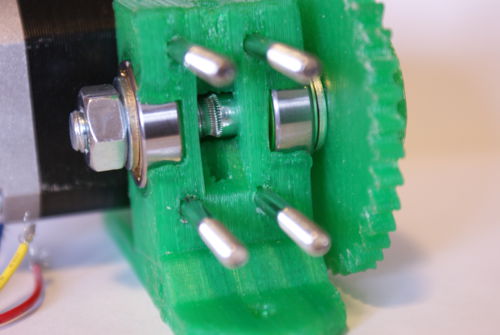
On how to make a Hobbed Bolt, see Making a Hobbed Bolt. That done, mount it like this:
|
- Note 1 - I prefer to use a Nylock nut on the end of the M8 shaft. Locktite should work as well, or a longer bolt with two nuts.
So far so good! If you add 3 or 4 M4 washers on each bolt before you put the idler block on, it will reduce the idler block travel when loading new filament, making loading new filament much easier.
Here's the test jig:
This extruder hit 16 kg - here's the results: M8 shoulder bolt - 7.0kg, adjusted tension, new springs - 11.0 kg,
Tightened springs, 3 trials:
15.5 kg, 16.5 kg, 15.25 kg
The final failure mode was the stepper running in reverse, as opposed to the filament slipping. That's quite promising.
The Hot End Mount
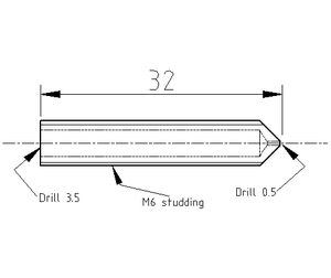
Attach a length of 16 mm PTFE using the two M (M3x35?) bolts to pin it in place. The holes in the ABS motor mount are 2.3mm diameter and are designed for thread-forming after being drilled to 2.5mm (2.3mm is very tight for M3 - M3's have a 2.387 bolt diameter and must be pre drilled 2.5mm for thread-cutting and even drilled wider for thread-forming, but plastic is very soft Threadinfo).
According to Nophead the holes should be drilled to 2.5mm, then you should insert the PTFE Insulator and drill a 2.5mm hole through both using the ABS part as guide. After the first hole is done insert a nail or second drill into the existing first hole to lock the teflon cylinder in place and prevent it from turning. After that use a M3 to thread-form the thread (one could also try to use a M3 tap drill (thread-cutter) and finish the mount, but thread-forming will do). The Teflon is very soft so it is very easy to thread-form. In the end the extruder should fit tightly.
Wade suggests that the nozzle can be built straight and is screwed into the PTFE (Teflon) cylinder from the bottom. There is no need for a PEEK bar or extra screws to hold the nozzle to the carriage.
Nophead's opinion is that unsupported PTFE may be OK for PLA but not for the higher temperatures and pressures ABS needs. He recommends a PEEK insulator with a PTFE liner or an external support which would need an adapter plate.
I use 8mm od brass rod, with a 4 mm ID melt chamber, insulated nichrome wire and furnace cement to hold it all together.
3D CAD Files
Here's the design files for the latest version:
- extruder body and idler block: File:M8 Extruder 3.zip
- 11 tooth drive gear and 39 tooth M8 hub driven gear: File:M8 Gears.zip
- alternative 11 tooth gear that should be better: File:Nophead gear with setscrew for wade extruder.zip
- (if you do not want to use a vise to support the M8 bolt) use this support for bearings, needed when using M3 tap: File:Pinchwheelwormdrilljig.zip
- Horizontal Wade Mount by tbuser
- Alternative driven gear by GilesBathgate
- You can also get the files from thingiverse although they may not be the most recent.
Finally, here's a spreadsheet to help calculate the proper feedrates: media:feedrates.ods | media:feedrates.xls
An updated version of the spreadsheet to use with Skeinforge, somewhat simplified. I vary the layer thickness, width/thickness and the two speed settings until I get a density near unity for nicely solid solid parts: media:Extruder Calcs 2010.07.13.ods
Variations on this design
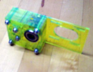
Alternative filament drive bolt: http://suddendevelopment.com/?p=68
Older versions
Here is a link to a previous version of this page that describes an earlier version of this extruder that uses an M4 shaft, and includes more details about pull testing the two versions: Geared_Nema17_Extruder_V0.5
