User:RobertKuhlmann/RepRap Morgan
Contents
Progress of my own Morgan
This bill of materials is based on the status of my own build of a RepMorgan.
You can see, how far I've got until now over here:

The actual Inventor-files (including the assembled Morgan from the picture above) can be found here: File:RepRap Morgan Inventor Files.zip
- Update: Wed. 08/14/2013
My struggle with Quentins pipe-supports and pvc-pipes lead me to redesign them, because I was unable to use his original files in a way they fit together acceptably (neither in Inventor nor in reality). I'll update the extended BOM.
deprecated: The bracket from Quentin's repository doesn't seem to fit. Here's a new version for the z-mount-bracket with an axis distance of 175mm instead of 190mm. This is since resolved in the repository (qharley)
- Update:Fri. 08/16/2013
The CAD-model now contains screws and gets more complete. Parts have realistic movement-parameters, so the completed model should be able to act like my real RepRap Morgan. I will update the extended BOM soon.
- Update: Sat. 08/17/2013
It's alive. The virtual Morgan has it's arms and toolhead and they can be moved by turn the steppers, just like in reality. Now I'm only a few parts from completing the model. I'll try to make the z-axis behave realistic too, but don't know how to do that - we'll see. Completing the building platform is the next task.
- Update: Sun. 08/18/2013
I've worked on the real Morgan prior to complete the virtual one. At this point I have to recommend a tool that kept my project going, while some of my parts broke or didn't fit. My pvc-pipe-supports, that were printed by a member of the community, didn't fit and two of them broke apart in my experiments. As if that wouldn't have been enough the z-mount-bottom broke too, when one of the smooth rods didn't fit as expected. Additionally the bed-z-mount-bracket had the wrong size (it's rod-distance was 190mm instead of the required 175mm). Instead of waiting for new parts I decided to repair them, using a special industrial glue. It consists of two components, a very fine granulate and a cyanoacrylate adhesive. In the very moment these two components come together, they build a very strong compound that is extremely hard and like welded to the surfaces it has contact with.
It can even be used to glue broken car bumpers. The plastic will break on any other position than the glued region. It can be found over here: Hosch-Kleber
Sorry for advertising this here, but it's a unique product with its abilities and one of my most important and frequently used tools for repairing and building. It's quite expensive though, but worth every single (Euro-)Cent.
With this I finished my real Morgan to the point of it's virtual brother this afternoon, without the need to reorder some of the printed parts. But reality hits me anyway: I only had 1m of T2,5 6mm drive-belt. Not enough for my Morgan, that requires app. 1,2m with its actual setup, and I had to order some more. And I need to buy some grub screws (replaced them with standard M3 screws for the moment).
My new designs for the top and bottom platform do fit as expected and I even don't need reprinted pvc-pipe-supports (but the newly designed ones would be ways better, of course).
I'm using a threaded rod for z-axis for the moment, because the bed-z-axis-bracket only fits with M8 nuts at the moment (or with Quentin's Alpen SDS solution, that isn't an alternative for me right now). So one of my Morgans first printjobs will be a new bed-z-mount-bracket that fits with my trapezoid thread and nuts. (Addendum: Or maybe it will be a threadless z-axis. Look at the forums for more on that topic: [1]).
- Update: Fri. 08/23/2013
I've designed a new building platform and integrated it with my new PCB for the heated bed (RK2). This PCB has a very homogeneous distribution of the copper traces.
I've tried a three-point-adjustment for the platform. It is not tested yet, but there are several spare montage holes if three isn't stable enough.
The copper traces of the heating-PCB are covered with isolating lacquer (Polyurethane) and for thermal contact to the upper aluminum building platform thermal heatsink paste is used. The aluminum building platform distributes the heat from below, so that there is a very homogeneous thermal distribution on the building surface.
The fan for the V3-toolhead is mounted already, but I didn't draw the printhead with Inventor yet.
- Update: Mon. 08/26/2013
Damn. My (60€) laser printer doesn't work anymore, just when I was printing the new PCB heated bed layout. I think I'll have it repaired until tomorrow. The real brother of my virtual Morgan lacks his heated bed though. For a few days.
I'll have to use M4 instead of M3 screws for the building platform adjustment of my real Morgan, because I didn't get knurled nuts in M3 in our DYI-store. The PCB-layout works with both (there's enough room for M4).
Detail pictures
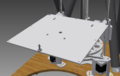
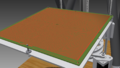
Mounting of building platform base
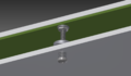
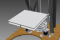
Platform adjustment in detail
Mounting of building platform
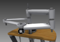
Arms with V3-toolhead and fan
PCB heated bed (new version)
Plain building surface
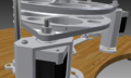
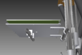
Detail shot of driver pulleys with grub screws


New ideas and notes
More stability for the frame
The stability of the frame could be improved by using steel cables or sth. similar to pull the supports together with some tension. Therefor there could be some wing nuts on the top platform, to tense the cables. (drawing will follow)
Multi Morgan
I'm planning to extend my morgan (once it is completed) to three print arms. With this configuration, it should be possible to use an extreme fine nozzle for the (slow) detailed work, a big nozzle for fast infills and a third one for support structures or e.g. to combine two materials with different properties into one print. Using the three printhaeds one after each other (they would collide otherwise) could make it possible to use the same electronic for all three printheads by completely switching the connections between the three sets of steppers, printheads and RAMP.
Long Morgan
It should be possible to extend the print height to almost any size, because there's no horizontal movement of the printbed. Therefore it should be possible to extend the print-height easily by placing the Z-Axis behind or in front of the drive-wheels, instead of above. The count of necessary modifications for that sounds not too big. Even the firmware would no be affected. The problem, that the print material on the top could become too cold (because of a greater distance to the heated printbed), could be avoided by using simple infrared lamps to keep the top portion of the print warm.
Air bearings
Already discussing air bearings in the forum I'd like to place this idea here too. I came across this idea, because air bearings are common in high precision applications and they don't wear out, reducing the TCO and preventing losses in print quality over the time.
(to be continued)