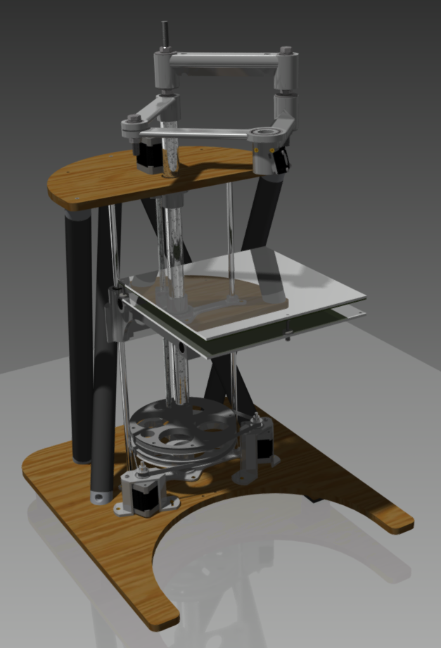
User:RobertKuhlmann/RepRap Morgan
Contents
Progress of my own Morgan
This bill of materials is based on the status of my own build of a RepMorgan.
You can see, how far I've got until now over here:

Update: Wed. 08/14/2013
My struggle with Quentins pipe-supports and pvc-pipes lead me to redesign them, because I was unable to use his original files in a way they fit together acceptably (neither in Inventor nor in reality). I'll update the extended BOM.
The bracket from Quentin's repository doesn't seem to fit. Here's a new version for the z-mount-bracket with an axis distance of 175mm instead of 190mm.
Update:Fri. 08/16/2013
The CAD-model now contains screws and gets more complete. Parts have realistic movement-parameters, so the completed model should be able to act like my real RepRap Morgan. I will update the extended BOM and the file archives with all project in a few minutes.
The actual Inventor-files (including the assembled Morgan from the picture above) can be found here: File:RepRap Morgan Inventor Files.zip
New ideas and notes
More stability for the frame
The stability of the frame could be improved by using steel cables or sth. similar to pull the supports together with some tension. Therefor there could be some wing nuts on the top platform, to tense the cables. (drawing will follow)
Multi Morgan
I'm planning to extend my morgen (once it is completed) to three print arms. With this configuration, it should be possible to use an extreme fine nozzle for the (slow) detailed work, a big nozzle for fast infills and a third one for support structures or e.g. to combine two materials with different properties into one print. Using the three printhaeds one after each other (they would collide otherwise) could make it possible to use the same electronic for all three printheads by competely switching the connections between the three sets of steppers, printheads and RAMP.
Long Morgan
It should be possible to extend the print height to almost any size, because there's no horizontal movement of the printbed. Therefore it should be possible to extend the print-height easily by placing the Z-Axis behind or in front of the drive-wheels, instead of above. The count of necessary modifications for that sounds not too big. Even the firmware would no be affected. The problem, that the print material on the top could become too cold (because of a greater distance to the heated printbed), could be avoided by using simple infrared lamps to keep the top portion of the print warm.