Universal Controller Board v1.1
Contents
- 1 Universal Controller Board
- 1.1 Build It
- 1.2 Congratulations! You have finished the common circuitry for the Universal PCB!
- 1.3 Technical
Universal Controller Board
RepRap uses the same printed circuit design for both the stepper controllers and the extruder controllers, but different components (and some common ones) are needed for each. This page describes how to put the common components together on the PCB and test them.
In fact, there is very little extra that needs to be added to the PCB that you will assemble from the instructions on this page and the complete stepper controller so, as you will see below, you can use a stepper motor to test the board at this stage, even if the board is actually going to end up as an extruder controller.
Build It
Soldering the first components onto the PCB
Complete components list
The file stepper-and-extruder.lst in ~your-id/workspace/electronics/Universal-pcb. is the component list created by KiCad, which you can use to order the parts you will need.
Here is the list, together with an indication of whether the component is needed for the stepper drivers (S), the extruders (E), or both (B).
R7 and R8 are only needed if you use an alternate design for end-stop, material-out, and extrude-speed sensors. Normally they are replaced by wire jumpers.
Common Components
| Component | Value | |
| U1 | 78L05 | |
| U2 | L298N | |
| U3 | PIC16F628 | |
| C1 | 1000uF 25v | |
| C2 | 100uF 12v | |
| C4 | 0.1uF | |
| R4 | 220R | |
| R2 | 10K | |
| D9 | LED | |
| D1 | 1N4005 | |
| D2 | 1N4005 | |
| D3 | 1N4005 | |
| D4 | 1N4005 | |
| D5 | 1N4005 | |
| D6 | 1N4005 | |
| D7 | 1N4005 | |
| D8 | 1N4005 | |
| K1 | CONN_3 | |
| K2 | CONN_3 | |
| P1 | CONN_2 | |
| P5 | CONN_2 | |
| P8 | CONN_2 | |
| P9 | CONN_4 | |
| P10 | CONN_5
|
Extruder Specific Parts
| Q1 | TIP110 |
| C3 | 1uF |
| R1 | 10K |
| R3 | 180R |
| R5 | 220R |
| R12 | 560R |
| D10 | LED |
| P4 | CONN_2 |
| P2 | CONN_2 |
Stepper Motor Specific Parts
| R10 | 4K7 | S |
| R11 | 4K7 | S |
| P3 | CONN_2 | S |
| Component | Value | Use |
| J5 | SIL10 | - |
| J6 | SIL10 | - |
| J7 | SIL10 | - |
| J8 | SIL10 | - |
</td> </tr> </table> </center>
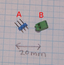
The connectors CONN_n are 2.54 mm pitch PCB transition connector pins like A here:
where n is the number of pins. One exception to this is P1, which should be a 2.54 mm pitch PCB screw connector like B. This is the 12v power connector.
Soldering - first stage
These are the first components to solder in:
| Component | Value |
| C1 | 1000uF 25v |
| C2 | 100uF 12v |
| C4 | 0.1uF |
| D9 | LED |
| P1 | CONN_2 |
| P5 | CONN_2 |
| P8 | CONN_2 |
| R4 | 220R |
| U1 | 78L05 |
| U3 | PIC16F628 |
Start by soldering in all the above components except the PIC (U3). The PIC should be mounted in an 18-pin DIL socket, as it will need to be removed and re-inserted for programming. Leave it in its anti-static packaging for the moment.
It can be hard to solder those components with flat bases that need to be soldered to the component side of the PCB. A good way to solve this is to tin round the hole where the component's leg is to go, then to tin the leg too. Now put the leg through the hole and touch the soldering iron onto the end of it sticking out of the bottom of the PCB. This melts the tinning and allows the component to be soldered in place. Alternatively, if the tinning on the PCB extends a bit beyond the periphery of the component, you can touch the soldering iron down there on the component side with the component a little proud of the PCB, then push it down when the solder melts.
Take particular care to get the polarity of the electrolytic capacitors and the LED correct. (The right-angled LED that I used and that you can see in the picture was the wrong way round; this is easily fixed by straightening its leads, turning it over in the holder, then bending them the other way.)
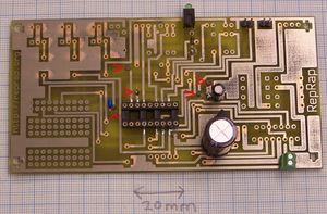
Here's what the board will look like when you've finished.
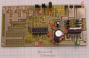
The red arrows indicate through holes. If you make the PCB yourself you will have to solder a short length of wire (a clipped component lead works well) through each of these. A commercial PCB should be through-plated and not need this.
Testing Rounds
First test - power
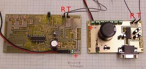
Wire the Communications and Power Distribution Board to your new circuit like this, but leave the PIC out of its socket and leave the transmit and receive wires disconnected.
Take Great Care to get the polarity of the power leads (red and black on the picture, and with red + and blue - labels) right.
Connect 12v power to the Comms board and check that there is 5v between sockets 14 and 5 of the PIC holder (- to pin 5, + to pin 14). This 5v comes from the regulator U1 (78L05).
Take the + probe of the voltmeter and check all the pin-sockets of the PIC connector relative to its socket 5. Most should be at 0v; one or two should be at about 3v. None should be more than 5v.
Switch off the power.
Second test - program chip
Now program up a PIC 16F628 (U3) with the file ~your-id/workspace/firmware/build/16f628/stepmotor/stepmotor.hex. This is the X-axis PIC control program for your RepRap machine. Observe the usual CMOS anti-static precautions when handling the PIC.
Connect transmit (T) on the Comms board to receive (R) on your new board, and recieve (R) on the Comms board to transmit (T) on your new board. Plug in the programmed PIC, notch to the right in the orientation shown in the picture above.
Switch on the power. The LED on your new board should light. Switch the power off again.
Third test - exercise command
Connect an RS232 cable between your computer and the Comms board.
Open the Eclipse Java development program. Open the Reprap project, and walk down the tree: src -> org.reprap. Right-mouse click on main.java and go down to Run as... -> Java Application.
Select Preferences from the File menu and set the port to the one your RS232 cable is connected to.
Click on the Axes tab and select Cartesian as the geometry. (The default is Null Cartesian, which is a dummy RepRap machine inside the software for testing purposes.) Cartesian is an honest-to-goodness real RepRap, such as the one taking shape on the end of your RS232 cable...
Click on OK in the Preferences box.
Turn on the power.
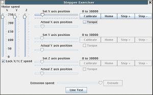
Now, from the Tools menu select Stepper exerciser. This should open a window that looks like this:
As you can imagine, this window allows you to move your RepRap machine around just by draging those pointers with the mouse. Drag the X-axis pointer to the right. The LED on your new board (which was on continuously) should begin to flash. Whenever one of the stepper controllers is moving its motor it flashes its LED, and this is what's happening. Of course you don't actually have a motor connected, or even the motor driver, U2 (L298N). But the PIC doesn't know that.
Close the program and all the windows, and turn off the 12v power.
Soldering - second stage
Remove the PIC and place it in its anti-static package.
The picture above shows the second stage of soldering complete. Start by putting links in the through-holes marked with the arrows. There is also a through-hole at B. This is a connector (P10) for a slave stepper driver should you want to drive more than one stepper off the board. But if you don't need that, just add the one through connector. Then add the links at A (in place of the optional R7 and R8).
Here are the remaining components needed at this stage:
| Component | Value |
| D1 | 1N4005 |
| D2 | 1N4005 |
| D3 | 1N4005 |
| D4 | 1N4005 |
| D5 | 1N4005 |
| D6 | 1N4005 |
| D7 | 1N4005 |
| D8 | 1N4005 |
| K1 | CONN_3 |
| K2 | CONN_3 |
| P9 | CONN_4 |
| R2 | 10K |
| U2 | L298N |
Solder in the resistor, the connectors, U2, then the diodes, in that order. Note the polarity of the diodes - bar to the right in the picture.
Put jumpers on connectors K1 and K2 as shown in the photograph (just above the letters A) - this tells the PIC that the axis that it thinks it is driving is not at either end stop.
Forth, fifth, and sixth tests
Fourth test
Reconnect the power connection to the Comms board, put a voltmeter on sockets 5 and 14 of the PIC holder (- to pin 5, + to pin 14), and turn on the power. The voltmeter should read 5v.
Take the + probe of the voltmeter and check all the pin-sockets of the PIC connector relative to its socket 5. Most should be at 0v; one or two should be at about 3v. None should be more than 5v.
Turn off the power.
Fifth test
Plug the PIC back in.
Reconnect the transmit and recieve lines. and re-run the Third Test above. The LED should still flash.
Turn off the power.
Sixth test
Connect a 4-wire bipolar stepper motor to the connector labeled C in the picture (P9). This can be one of the RepRap steppers that you will be using, or just a spare for testing taken from an old printer, say. Any stepper with a coil resistance of more than 10 ohms and less than about 50 ohms should work. Connect one coil between pins 1 and 3 of P9, and the other between pins 2 and 4.
Repeat the third test, but first drag the motor speed bars on the left of the window down to about half way. The LED should flash and the motor should rotate (put some sticky tape on the spindle so you can see what's happening).
Finally, select the X-Axis "Home" button in the window. The motor should rotate continuously in the opposite direction.
Pull off the left-hand jumper (on K2; the one on the left in the photograph). The motor should stop as this is the signal to the PIC that the endstop has been reached.
Congratulations! You have finished the common circuitry for the Universal PCB!
Technical
Circuit diagram and PCB
All the KiCad files for this are in ~your-id/workspace/electronics/Universal-pcb. In particular, if you open stepper-and-extruder.pro in that directory in KiCad you will have both the circuit diagram and the PCB layout available.
You may have acquired the PCB from a commercial supplier, in which case carry on below. To make one yourself, follow this link.
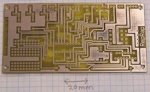
Here's what the PCB will look like when you start. The side the components go on is the one with the lettering (this one):
PIC 16F628 Pinout:
One obvious common component is the PIC - a 16F628. But some pins do different things in the two devices:
[i] = input, [o] = output, [b] = bidirectional
| Pin | Stepper controller | Extruder controller |
| RA0 | L298 [o] | L298 (Fan) [o] |
| 1 | Sync [b] | Thermistor [i] |
| 2 | L298 [o] | L298 (Fan ) [o] |
| 3 | Sync [b] | Heater [o] |
| 4 | LED [o] | LED [o] |
| 5 | Max [i] | Material out (input only) [i] |
| 6 | - | Thermistor [i] |
| 7 | - | Thermistor [i] |
| RB0 | Min [i] | Slotted-wheel for extrude speed [i] |
| 1 | Rx [i] | Rx [i] |
| 2 | Tx [o] | Tx[o] |
| 3 | L298 Enable [o] | L298 Enable [o] |
| 4 | L298 [o] | L298 (Extrude) [o] |
| 5 | L298 [o] | L298 (Extrude) [o] |
| 6 | - | - |
| 7 | - | - |
Board Modifications
Without L298N
Components marked (A) are for an alternate extruder design without an L298N, and so can normally be left out. (This extruder is cheaper to make, but can't reverse the extrude motor - to make it just leave out U2, D1...D8, and P9, then add in the (A) components.)
| R6 | 220R | A |
| R7 | 220R | A |
| R8 | 220R | A |
| R9 | 220R | A |
| Q3 | TIP110 | A |
| Q2 | TIP110 | A |
| P6 | CONN_2 | A |
| P7 | CONN_2 | A |
Easy Breadboard
Ignore components J1 ... J8; they are just SIL connectors that were added to the circuit diagram to create the pattern for the breadboard area - you don't actually need to solder connectors into those holes (though you can if you want - then you can breadboard without soldering).
Parts For Easy Breadboard
| J1 | SIL10 | - |
| J2 | SIL10 | - |
| J3 | SIL10 | - |
| J4 | SIL10 | -
|
-- Main.ZachSmith - 11 Feb 2007
