UNAL FDM
|
English • العربية • български • català • čeština • Deutsch • Ελληνικά • español • فارسی • français • hrvatski • magyar • italiano • română • 日本語 • 한국어 • lietuvių • Nederlands • norsk • polski • português • русский • Türkçe • українська • 中文(中国大陆) • 中文(台灣) • עברית • azərbaycanca • |
Release status: working

| Description | Colombian designed 3d printer
|
| License | |
| Author | |
| Contributors | |
| Based-on | |
| Categories | |
| CAD Models | |
| External Link | [url aqui]
|
Contents
Introduction
En construcción
Improvements over other printers
En construcción
- Uses shorter smooth rods lowering the build costs.
- Once assembled, it forms a compact, solid structural unit that can be transported as a block.
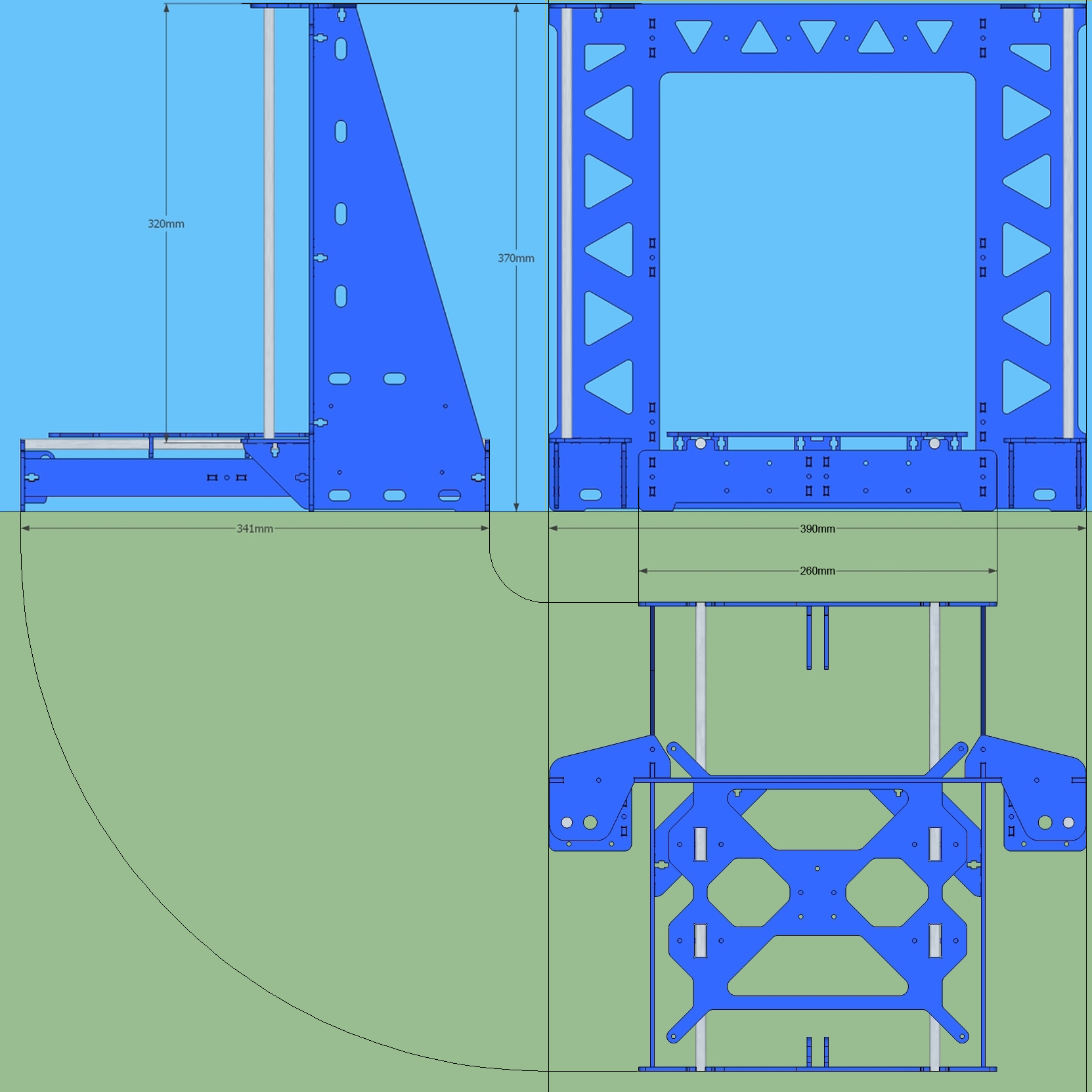
Main dimensions (frame version 2.0)

Frame versions
The P3Steel frame design has evolved since it release. Here are the various versions and how they differ:
Version 1.2: Leonardo, original printer, the one I made.
Version 2.0: After some requests from a Spanish group building around 30 printers, I have modified the bed, now it holds with 4 LM8UU instead of 3 and it has also a system to level with 3 points instead of the original 4, it should be easier with this new design. I kept the original 4 points also just in case someone still wants to use them. I included in the gallery some 3D renders of the new bed. The rest of the printer is exactly the same as version 1.2
Everything snaps together and holds with M3x12 screws (mainly), I also used nylon self locking nuts to prevent future problems due to vibration.
The printer uses 8mm chromed smooth rods (Z axis: 2 x 320mm, Y axis: 2 x 341mm and X axis: 2 x 375mm) and only two M5 threaded rods (295mm approx. each since depends on motor coupling and if you want some to stick out through the top) for the Z axis, printed parts required came from a standard Prusa i3, you only need the parts for the X axis assembly and the extruder.
The printer structure is assembled quite fast and needs no adjustments. The electronics are installed on either side of the frame, horizontally, holes provided are for an Arduino mega and RAMPS 1.4. Motors are NEMA 17, GT2 pulleys, LM8UU and 608zz bearings. Hotend is budas type, but depending on the extruder plastic parts, will also accommodate J-head and E3D hotends. The hotbed is the standard MK2B.
Version 2.01 (by AndrewBCN): this is exactly the same as version 2.0 except for the changes listed below.
- The interference between the Y stepper and the M3 nyloc nut holding the Y stepper support has been solved by stretching the support by 2mm (see the P3Steel Y axis assembly page for details).
- The frame has been stretched by 9mm, meaning the Y-axis 8mm smooth rods should now be 350mm long (same as the original Prusa i3), and not 341mm long anymore (4mm have been added to the front and 5mm to the back).
- Two 3mm holes have been added along the sides of the front Y-axis subframe, one on each side, to attach optional accessories / cable ties to the frame.
- The practically useless part that could eventually be used as a Y belt holder has been deleted (there are much better designs that can simply be printed).
CAD file for version 2.01: File:PRUSA i3 steel 3mm lasercut 2.01d irobri.dwg (generated with DraftSight 2014, use a recent version of DraftSight or SolidWorks to open)
(see the Discussion tab for justification of these changes)
Version 2.5 (by AndrewBCN): this is a dual Bowden extruder capable, slightly enlarged P3Steel variant derived from my earlier P3Steel 2.01 variant. In keeping with the KISS philosophy of the original P3Steel and avoiding changing something that works, as few changes as possible were made in relation to version 2.01:
- The frame is 10mm wider. This is achieved by making the central plate and the two Y-axis end plates 10mm wider. Note that the distance between the Y-axis smooth rods remains the same..
- The frame is 10mm taller. This is achieved by making the central plate and the two side panels 10mm taller.
- The holes to mount the Arduino Mega 2560 + RAMPS board are 10mm higher, increasing the clearance for the USB cable.
- There is an added cutout in each of the side panels to keep the frame weight in the same range as the original P3Steel 2.01.
- There are two stepper motor cutouts, one on each side panel, for mounting two optional Bowden extruders.
- All screw holes now have the same diameter, 3.2mm (the holes for the electronics on the side panels were previously specified at 2.6mm diameter for later tapping with M3 threads, this is now deprecated).
Apart from the minor changes above, nothing else is changed.
Note that making the printer 10mm wider and 10mm taller does not really result in an increase in the print envelope, rather it makes it easier to achieve the original print envelope of the Prusa i3 (200 x 200 x 200mm or 8l).
Also note that use of the Bowden extruder stepper mounts is optional. Basically the P3Steel 2.5 DXL can still be built exactly like the original P3Steel, with a single Greg's Wade's Geared Extruder on the X-carriage, or one can use a single Bowden extruder mounted on either sidepanel, or two Bowden extruders mounted on both sidepanels.
CAD file for version 2.5 (zipped): File:PRUSA i3 steel 3mm lasercut 2.5DXL e irobri.dwg.zip (generated with DraftSight 2014, use a recent version of DraftSight or SolidWorks to open)
(see the Discussion tab for justification of these changes)
Also note that versions 3.0 and 4.0 mentioned below are not derived from either versions 2.01 or 2.5, they are independent developments by their respective authors.
Version 4.0 (By Alvaro Rey and Daniel Torres) From Version 3.0 (By Ghosthawk) with the listed changes
- The extruder no longer hits the Z axis top bracket
- Y axis belt tensioner ( that may be placed printed or metallic )
- Weight reduction cutting as much material as possible
- Holes to bolt to the PSU
- Electronics as high as possible so that the cables are well hidden LCD
- Holes in the top bracket of the Z axis to position bearing
- Holes in the top bracket of the Z axis to place spool holder
- Axis movable to lose the least footprint
- Y axis bed it's suitable to install 20x20 heated beds or 20x30 heated beds
- The hole for the motor connector has been enlarged , allowing install engines below 70 OZ
- Bed with option for 3 or 4 bearings
- Bed with choice of 4 or 3 leveling points
- Holes for Zip ties was added to the main frame
The Y-Axis rods have been changed, now uses 10mm rods ans LM10UU lineal Bearing We recomended use aluminum beds for y axis.
We test aluminum frame too in 3mm. It works just the same
20x30 Frame - the Y-axis 10mm smooth rods should now be 510mm long
This version use aluminum beds, in orther to reduce weight in Y-Axis
P3steel toolson edition
The P3steel toolson edition uses the unmodified steel parts from a P3Steel v2.01 or v2.5 frame, but nearly every 3d printed plastic part has been improved:
- "P3steel - toolson edition" discussion on the RepRap forums
- "P3steel - toolson edition" on Thingiverse
Assembly animation
<videoflash>In_Q6NkX3fs</videoflash>
On YouTube: https://www.youtube.com/watch?v=In_Q6NkX3fs
Assembly manual
- Assembly PDF: File:Montaje PSteel.pdf
- Online manual: Complete assembly manual online
Modification to use Spindles
To use 10mm diameter spindles we need to separate the smooth rod and the spindle, leaving room for the nut and bearing parts in the X axis. Therefore some adaptation is required. We have designed a few pieces for use them in the original structure, so the changes were minimal.
This file File:Adaptacion Husillos.zip contains the OpenSCAD design files along with some other files to support for visualizing the set.
Where to buy
- 3DESPANA.COM Full kit available send to worldwide Good price.
- Orballo Printing Worldwide shipping!
- IBEROBOTICS Shop - Complete kit. Optional mounting service.
- RepRap Forum https://groups.google.com/forum/#!msg/asrob-uc3m-impresoras-3d/waJV15JftZ4/TTAb1bQ4mPQJ (Stainsless Steel, S235, Rods...) We ship to EU.
- iFusionShop
- KITPRINTER3D (required vitamins to make a P3Steel from a Prusa i3), complete kits starting at 409€ VAT included, check our XL version with 300x200mm printing surface.
- CREATEC 3D
- MakerShop BCN in Barcelona, Spain. Version 2.01 of the frame in structural steel only + 8mm stainless steel smooth rods, ships to EU, with reasonable rates.
- Impresoras 3D en México (CIUDAD DE MEXICO) D.F. Kit Prusa i3 Steel con marco en acero estructural, varillas acero inoxidable.
- HTA3D Full kit for P3Steel, 20x20x21cm actual printing volume, direct drive extruder with Mk8 and hotend V6, cable chain and much more.
- REPRAP.PT in Lisboa, Portugal. Electronic parts.
|
|
Proyecto Clone Wars |
Related
- The P3Steel is not to be confused with the 3Done P3.