ThermoplastExtruder
-- Main.AdrianBowyer - 02 Nov 2005
Contents
The RepRap Polymer Extruder Head
Version 2, 2nd November 2005
Summary
This document describes the Version 2 RepRap polymorph extruder head. It is intended to allow other researchers to reproduce the results. The head was designed to be made by the RepRap rapid prototyper itself, and thus consists of standard parts plus rapid-prototyped components. There were also a few parts that required other tools to make; the intent of the design was to make these parts as simple as possible, to minimise the tools needed, and to keep their number as small as possible. The head extruded a stream of Polymorph polymer about 0.5 mm in diameter at a temperature of 180 oC and a rate of up to 4 mms-1. The extruder is experimental, in that many parameters for it (particularly in the software) are user-set and controlled, whereas in a finished RepRap machine these would permenantly be set to defaults.
Introduction
My Version 1 RepRap polymorph extruder head has the great virtue that it works, but it also has some shortcomings. The main ones are that it is quite expensive to make, that it has a lot of moving parts, and that some of the components are rather hard to obtain.
Consequently I decided to revisit and idea of Vik Olliver's that he blogged on 14 June 2005. Here is his original sketch:
This is so neat that I attempted to make such a design before I made the Version 1 Extruder, but it didn't work. The problems were twofold:
- The resistance of the heated nozzle extruder (which would be just below the bottom of Vik's drawing) was too great, and
- The screw tended to chew up the polymorph rod, a problem from which the device couldn't recover.
However, when I made Version 1, I discovered that keeping the polymorph fine-nozzle very short reduced flow resistance dramatically. So I thought that maybe, with that new nozzle, Vik's idea could be made to go.
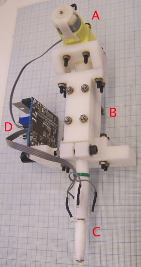
It turns out that it can. Here is a picture of the finished device:
A geared electric motor (A) drives a screw chamber (B) in which a threaded rod is forced against a rod of polymorph. As the thread turns, the polymorpf is pushed downwards to a heated nozzle (C) and is extruded out of the bottom. The control electronics is shown at (D).
This Version 2 design has many fewer parts than Version 1, those parts are cheaper and easier to obtain, and the overall mass of Version 2 (just under 200 g) is less than half the mass of Version 1.
The heated nozzle is identical to that used in the Version 1 extruder, and the electronics is only changed by the addition of one potentiometer. The software in the electronics is also identical to that used in the Version 1 extruder. Despite these similarities and identities, full descriptions of all the parts are given in this document for completeness.
%RED%OBVIOUS WARNING: the heated nozzle C gets very hot (almost as hot as a soldering iron). It is a bad idea to touch it or the wires leading to it when the machine is working or has just recently been switched off.
LESS OBVIOUS WARNING: The motor is geared down to drive the screw-thread very slowly. This means that, even though it is a fairly weedy motor, it is turned with a considerable torque. It is well-nigh impossible to get one's fingers in the works, but if one manages to do so, the motor will just keep going and injuries will occur.
WARNING FOR NON-CHEMISTS: Nozzle C is partially made from PTFE. PTFE is stable up to 250 oC. Above that it breaks down into various gasses, some of which are quite toxic. The extruder should not be operated above 250 oC.%ENDCOLOR%
High Temperature Nozzle
As just indicated, this is identical to the nozzle for the Version 1 Extruder.
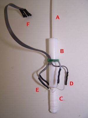
Here is a close up of the heated nozzle (C in the picture above) with a 3 mm Polymorph polymer rod being fed into it.
The 3 mm Polymorph rod to be extruded (A) enters a PTFE tube (B). A smaller brass tube (C) is screwed into the bottom of the PTFE tube. The bottom end of the brass tube forms a fine nozzle. The brass tube is wrapped in PTFE tape, on top of which is wound a coil of nichrome heater wire. The ends of the heater wire can be seen at D. More PTFE tape is wound over the wire to keep it in place and to act as a thermal insulator.
A glass-bead thermistor (the slight bump on the bottom left of the brass tube C) is held against the brass tube by more PTFE tape; the wires from the thermistor can be seen at E. A short four-way ribbon cable is connected to both the heater and the thermistor and terminates in a connector at F. This connector interfaces with the control electronics. The ribbon cable is held to the PTFE tube by the green cable tie.
The nichrome wire heats the brass (C), melting the polymer within it. The PTFE tube (B) guides the solid polymer rod (A) into the brass and insulates the rest of the machine from the high temperature of the brass. As the rod (A) is forced into the top of the PTFE it acts as a piston driving molten polymer out of the nozzle. The thermistor monitors the temperature of the brass and allows it to be thermostatically controlled.
Note the bare flying nichrome wires just below D. These need to be kept clear of the rest of the assembly as shown. They get very hot when the heater is first turned on, and must be in the open air.
To build the high-temperature nozzle, start with the brass tube. This is made from 6 mm diameter brass rod (most of the brass parts of the RepRap machine can be made from this size of rod), but could alternatively be made from a length of M6 threaded brass studding, or from an M6 brass screw from which the head has been hacksawed off.
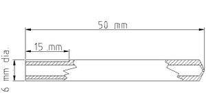
Here is a drawing of the brass tube as it should be when finished. This drawing was created with the open-source version of QCad, and is in the Mechanics folder of the download (see below).
The brass part of the nozzle is a tube 50mm long and 6mm in diameter. The internal hole diameter is 3mm. The left-hand end is threaded M6 for a length of 15 mm. The right-hand end is a fine nozzle formed by a small diameter hole in the end. This is made by drilling the hole, turning a cone on the outside, and then drilling the 3mm hole down the middle from the left. The nozzle is formed by the conical end of the drill, the fine hole, and the external cone.
It was found to be very important to keep the length of the fine-diameter hole that forms the nozzle as short as possible. This is because the resistance to the flow of a viscous fluid (and molten polymer is highly viscous) is very dependent on the length of any tube through which it has to flow.
The diameter of the nozzle is a compromise: a large hole allows material to be deposited fast, but reduces the resolution of the machine; a small hole reduces material deposition rate but allows greater resolution. Most commercial machines use a diameter just under 0.5 mm. Of course, a RepRap machine could have two nozzles: one for coarse infill, the other for surfaces and fine detail. Note that the extrudate will end up slightly larger than the diameter choosen because of die swell (molten polymer is not a Newtonian fluid, it is viscoelastic; this means that when it is momentarily extruded through a fine nozzle it 'remembers' its former diameter and swells a bit larger than the nozzle diameter from which it has emerged). I have not listed tools in the parts section, as all of them are completely standard and widely available. However, fine drill bits are sometimes hard to find, so I have included suppliers of 0.5 mm (and other small) drills.
Start by turning the right-hand end of the rod square, then mark the end with a fine centre drill in the lathe's tailstock. If a fine centre drill is not available, a 1 mm drill projecting just a couple of mm from the tailstock chuck would work just as well. Make only a shallow dent. Next drill the fine nozzle hole using an 0.5 mm drill (other diameters could be used, both finer and coarser) to a depth of about 3 mm. This could be done in the lathe, but I found it easier to use a minidrill in a drill press, with the brass rod held vertically in a vice. Fine drills are very delicate - you need to use minimum force, to make sure you don't bend the drill, and to back off repeatedly to clear the swarf (i.e. use a woodpecker cycle).
Next turn a cone on the end of the rod to form the nozzle. The angle of the cone needs to be rather shallower than the cone created by the 3 mm drill bit that will be used to create the large hole, as in the diagram above. This allows the nozzle's fine-diameter hole to be as short as possible, while giving the greatest strength. When the cone has been turned, the nozzle hole may need to be cleaned again with the fine drill used to make it.
Next turn the left end of the rod flat, and mark a centre on that. Remove the rod from the lathe chuck and offer the 3 mm drill to be used to make the large hole up to the side of it. Position it so that the tip is about 0.5 mm inwards from the tip of the turned cone, then wrap some sticky tape round the other end of the drill to mark the length of the rod. Put the rod back in the lathe and drill it until the tape just touches the end of the rod. That way the hole will be as deep as possible without breaking through at the nozzle end. Once again, it may be necessary to clean the nozzle hole with the fine drill used to make it.
I found it worth wrecking one or two trial nozzles to end up with one where the fine nozzle hole was as short as possible to maximise flow.
%GRAY%If studding or a screw is being used to make the brass part of the nozzle (as opposed to plain rod), this paragraph can be ignored. Cut an M6 thread to a length of about 15mm on the rod on the left end. If a lathe is being used, a good way to get the M6 die square for this operation is to put the die in the lathe chuck squaring it up with a rule across the face of the chuck (%RED%unplug%ENDCOLOR% the power first...) and to put the rod in the tailstock. Then put the lathe in its fastest gear to make the chuck easy to turn by hand, and release the tailstock so that it will slide along the bed. Then push the rod against the die and - keeping a slight pressure on - rotate the chuck by hand to cut the thread. Rotate it anti-clockwise occasionally to clear the swarf.%ENDCOLOR%
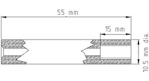
Next make the PTFE tube. Here is a drawing of it (again this is in the Mechanics folder of the download below).
The PTFE tube is 55 mm long and 10.5 mm in diameter. It has a 3 mm hole right through it, and the last 15 mm are drilled and tapped M6. A small cone is cut at the left-hand end so the polymer rod to be extruded can engage in the 3 mm hole more easily. You may find it easier to get 10 mm diameter rod than 10.5 mm; if so only one change needs to be made to the design - this is discussed in the section on the nozzle clamp below.
Cut a length of 10.5 mm diameter PTFE rod and turn the ends square to a length of 55 mm. Drill a 3mm hole right through, and then a larger hole (5 mm) to a depth of 15 mm. Tap this hole M6. (Again, line things up with the lathe: unplug the power, put the tap in the tailstock, set it free to slide, press it against the 5mm hole, and turn the chuck to cut the thread. Do half a turn anti-clockwise every so often to clear the swarf.)
Use a large drill bit to open out the left-hand end of the 3 mm hole into a cone by hand as shown above. This makes it easier for the end of the polymer rod to locate when it is fed into the hole.
Thoroughly clean the brass and PTFE parts. Any swarf that remains in them will get swept down by the flowing polymer and will block the nozzle. Screw the parts together tightly, but not so tightly that it strips the threads in the PTFE.
Now wind the heating coil round the brass. I used 0.2 mm diameter nichrome wire, but slightly different diameters would work just as well. Use a multimeter to measure off a 12 ohm length of the wire and cut it (it will be about 200 mm long).
Hold the PTFE tube in a vice with the brass rod projecting horizontally.
Then wrap a helix of PTFE tape round the brass rod so that the helix overlaps itself to give two thicknesses, one on top of the other. This tape is to electrically insulate the nichrome from the brass. If a threded rod is used the PTFE will pull into the valleys of the thread; this is okay.
Use a blob of Blu Tack to stick one end of the length of nichrome wire to the PTFE tube where the brass rod is screwed into it and wind the wire in a helix down the brass. If a threaded rod is used you can simply wind it in the valleys of the thread, otherwise you must try to get the pitch reasonably even. Stop about 5 mm from the nozzle end of the brass and wrap a piece of PTFE tape round the last few turns to secure them. Wrap another helix of PTFE tape round the nichrome coil, again overlapping to get two thicknesses. Lead the free bottom end of the nichrome wire straight back up the outside of this to the top of the brass, and wrap more PTFE tape round that to secure it. You should now have something that looks like the photograph above, but without the ribbon cable and without the thermistor wires on the left.
Next, the thermistor. I used the glass-bead thermistor in the Parts List below. It had a beta value of 3500, a room-temperature resistance of about 6 kilohms, and a resistance of about 100 ohms at 170 oC. You could use a different one if need be (there's a spreadsheet in the Electronics section below to help with the calculations), but it needs to be rated up to 250 oC. Carefully wrap the thermistor's leads in PTFE tape to insulate them, then placed the thermistor against the bottom of the brass in the 5 mm gap left below the nichrome coil. Wrap yet more PTFE tape round it and its leads to hold them and to insulate the device. I found that one doesn't need too much insulation - the nichrome is going to have about an amp put through it, and 12 watts will heat things pretty quickly - but the more one has, the more efficient the device will be.
Solder a 150 mm length of four-way ribbon cable to the thermistor leads, using fine heat-shrink sleeving to insulate the join. Soldering to the nichrome is a bit more problematic - solder doesn't wet nichrome... However I found that wrapping both the nichrome and the bared end of the ribbon cable round a single piece of thicker wire (a cut-off resistor lead worked well) would allow solder to be run over the lot (use a little extra flux if it is reluctant to do so) and made a good solid connection. Once again, use heat shrink to insulate them both, but leave all the unsoldered nichrome above the coil in free air - it gets hot.
Attach the ribbon cable to the PTFE tube with a cable tie, taking care not to attach it too near the hot end...
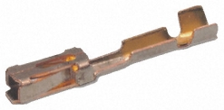
Solder connectors onto the free ends of the ribbon cable. A good cheap way to do this is to get a pack of crimp connectors for unshrouded shells like this:
They are about 12 mm long and 2 mm across. Solder them to the ends of the wires, then put heatshrink sleve flush with the open end round them to insulate them. You finish up with each wire having a neat small individual connector on the end. The connectors are listed in the Parts Section below.
Finally - measuring from the connectors you've just created - check that the resistance of the heater is still about 12 ohms (that is, check that it's not shorting on the brass tube), and check that the resistance of the thermistor is its room-temperature value.
Drive mechanism
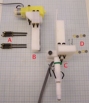
The Version 2 drive mechanism is radically simpler than that for Version 1. Here is an exploded view of it just before the final assembly step:
Four 55 mm lengths of M3 studding (A) have springs on them retained by nuts and washers. These pass through the motor-driven screw block (B) holding it to the polymorph rod guider (C - shown with the extrusion nozzle fitted). The nuts and washers that go on the end of the M3 studding are shown at D. The springs give the device some compliance; slight irregularities in the polymorph rod as it passes through are accommodated, and the force between the rod and the screw-thread driving it is kept roughly constant.
All the rapid-prototyped parts for the extruder were designed using the open-source Art of Illusion software package, and the .aoi design files for them are in the Mechanics section of the download below.
