Temperature Sensor v1.1
Contents
Temperature Sensor v1.1
Overview
<div class="thumb tright"></div>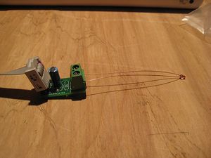
- You'll need a soldering toolkit to do most of this.
- Read our Electronics Fabrication Guide if you're new.
Get It!
Raw Components
Files
You can download the electronics files from Sourceforge.
This file contains the following:
- GERBER files for getting it manufactured
- PDF files of the schematic, copper layers, and silkscreen
- Eagle source files for modification
- 3D rendered image as well as POVRay scene file
- exerciser code to test your board.
Schematic
<div class="thumb tright"></div>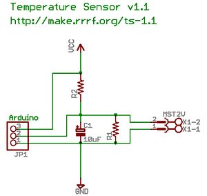
Interface
| Pin | Function |
| +5 | This is the pin to supply +5 volts on. |
| S | This is the signal pin. It will output a voltage between 0 and 5 volts that correlates with the temperature. |
| G | This is the ground pin. |
Signal Values
The thermistor circuit is a voltage divider that can be read with an ADC such as the one on an Arduino board. That value can then be run through a formula to get the temperature in degrees. This circuit has been documented in full detail in a blog entry by nophead.
Thermistor Values
You can use a variety of thermistors with your temperature sensor.
Build It
Board Bugs
- No bugs yet, please report any you find to the forums.
Printed Circuit Board
<div class="thumb tright"></div>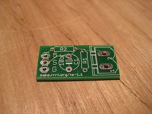
You can either buy this PCB from the RepRap Research Foundation, or you can make your own. The image above shows the professionally manufactured PCB ready for soldering. Its also really cheap since it is so small!
Components
<div class="thumb tright"></div>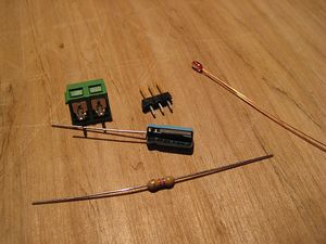
<iframe width='500' height='330' frameborder='0' src='http://spreadsheets.google.com/pub?key=pmEMxYRcQzzATwbOb71BmGA&output=html&gid=37&single=true&widget=true'></iframe>
Soldering Instructions
<div class="thumb tright"></div>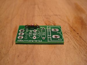
R2
The value of R2 will depend on your thermistor. If you use the RRRF kit, it will be 4.7K ohms.
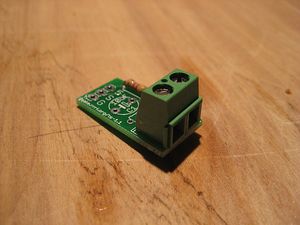
Screw Terminal
Make sure you insert the connector correctly: with the opening facing the outside of the board.
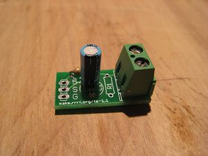
C1
Electrolytic capacitors have a polarity. Make sure the stripe on yours matches the one in the picture.
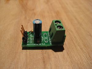
Headers
Insert the headers and solder them. If they face at an angle away from the board, that will help in attaching connectors to it later.
Test It
Now that you have your temperature sensor tested, you'll want to test it.
Wire it up!
<div class="thumb tright"></div>The wiring is very simple:
- Wire 5 to +5v on the Arduino
- G to GND on the Arduino
- S to Analog 0 on the Arduino
you're done!
If you have an IDC connector laying around, its even easier! Just plug it into the connectors!
Upload firmware to Arduino
Create a new sketch and copy/paste the code below into it. Upload it to your Arduino.
The code below is for the standard EPCOS 100K thermistor that comes from Mouser. If you use a different thermistor, or are using different resistors in the board, we have a python script that you can run to generate new values in the lookup table, or you can grab a pre-calculated table from the thermistor page.
#define THERMISTOR_PIN 0 #define NUMTEMPS 22 short temptable[NUMTEMPS][2] = { // { adc , temp } { 1 , 608 } , { 60 , 176 } , { 70 , 166 } , { 80 , 157 } , { 90 , 150 } , { 100 , 143 } , { 110 , 137 } , { 120 , 131 } , { 130 , 125 } , { 140 , 120 } , { 150 , 115 } , { 160 , 110 } , { 170 , 105 } , { 180 , 100 } , { 190 , 95 } , { 200 , 91 } , { 210 , 86 } , { 220 , 81 } , { 230 , 75 } , { 240 , 70 } , { 250 , 64 } , { 300 , 4 } }; void setup() { Serial.begin(9600); Serial.println("Starting temperature exerciser."); } void loop() { int rawvalue = analogRead(THERMISTOR_PIN); int celsius = read_temp(); int fahrenheit = (((celsius * 9) / 5) + 32); Serial.print("Current temp: "); Serial.print(celsius); Serial.print("C / "); Serial.print(fahrenheit); Serial.println("F"); Serial.print("Raw value: "); Serial.println(rawvalue); Serial.println(" "); delay(1000); } int read_temp() { int rawtemp = analogRead(THERMISTOR_PIN); int current_celsius = 0; byte i; for (i=1; i<NUMTEMPS; i++) { if (temptable[i][0] > rawtemp) { int realtemp = temptable[i-1][1] + (rawtemp - temptable[i-1][0]) * (temptable[i][1] - temptable[i-1][1]) / (temptable[i][0] - temptable[i-1][0]); if (realtemp > 255) realtemp = 255; current_celsius = realtemp; break; } } // Overflow: We just clamp to 0 degrees celsius if (i == NUMTEMPS) current_celsius = 0; return current_celsius; }
Try it out
<div class="thumb tright"></div>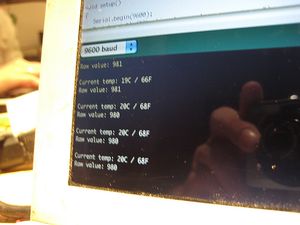
Start up your Arduino, and open the serial monitor. The exerciser code reads the thermistor every 2 seconds and outputs the current value of the thermistor, as well as the estimated temp. The thermistor code is only accurate at higher temperatures, so get some sort of heat going. I recommend a heat gun, but a lighter will also work in a pinch. Heat it up, and watch the terminal. The most important thing to check is that it is actually changing with temperature and is relatively accurate.
If so, then you've successfully built your temperature sensor. Congratulations!
History
Previous Boards
- This is an incremental upgrade of Temperature Sensor v1.0
Changelog
- Removed component values from silkscreen to reflect fact that they may change based on thermistor.
- Changed to screw terminal for easy thermistor connection.