Teensy Breadboard
Contents
Teensy Breadboard

Combines a $16 ATmega32U4 based carrier from http://www.pjrc.com/teensy with Pololus on a solderless breadboard. Runs Teacup through integrated USB using LUFA serial at 38400 baud. (Teensy is capable of 12MBit/sec communication per [[1]]. Tested at 230400 baud with CoolTerm, and 250000 Baud with Pronterface with modified Teacup using Teensy's usb_serial* routines.) Possible (and recommended) upgrade path to the AT90USB1286 on a $24 Teensy++ towards Teensylu and Printrboard compatibility. Possible upgrade path to a $19 32 bit ARM Cortex-M4 48MHz processor on Teensy 3.0, http://www.pjrc.com/store/teensy3.html
Philosophy
Some of the most expensive parts for a RepRap are the steppers and stepper drivers. If you settle on either NEMA14 or NEMA17 steppers, you can buy them with some stepper drivers early in the RepRap process. Before committing to a RepRap design, or even to Filament Deposition Manufacturing, you could play with the steppers and control with an eye towards other projects. If you think automated steppers would be fun to play with, you can start with a single stepper, matching driver, a piece of breadboard, and a USB-capable cpu.
Price, commitment, end-of-lifecycle-wise, $9*4 for the drivers + $16 for the CPU and $4 for a Protected Mosfet gets you most of what you need for the electronics for only $56 worth (2012-11-01) of very reusable components.
On the electronics side, it all fits in a single solderless breadboard ($4 Ebay 2012-11-01) with a little usb-capable carrier like the Teensy. The Teensy 2.0++ might be easier to build firmware for, since it matches the atmega1286usb chip already used in the in the Teensylu and Printrboard. I used the smaller Teensy 2.0 since I already owned one.
My Wallace uses 4 NEMA 14s ($16 from Pololu) and an expensive MakerBot high torque NEMA17 ([17Y402S-LW4-01] (overkill) on my Wade's extruder.
The design is future proof in that you could easily add a couple more axes, extruders, fans, or an upgraded processor, as RepRap or your needs evolve.
Firmware
- Teacup/Gen7 branch: https://github.com/triffid/Teacup_Firmware/tree/Gen7
- I have some modifications are in https://github.com/drf5n/Teacup_Firmware/tree/Gen7 but the main Gen7 branch works.
Here's a screenshot of Teacup/Gen7 working on a Teensy 2.0:

Parts
- 1 - 830 point breadboard
- 1 - Terminal block,
- 4 - Pololu_stepper_driver_board#List_of_Boards Stepper drivers
- 1 Teensy 2.0 breadboard (Teensy 2.0++ should also work)
- 1-3 (*1) - VNP49N04 Fully Protected Mosfet [Datasheet][Digikey] *2
- 2 - 2.7Kohm resistors R2 *3
- 1-3 1k resistors for heater pin feedback protection.
- Many - Miscellaneous jumpers
(*1 - 1-3 MOSFET circuits, depending on whether or not you have a heated bed or fan. More heater/spindle circuits are possible, depending on pin availability)
(*2 Other MOSFETS could certainly be used. But fully protected, logic-level, ESD-protected MOSFETS reduce component count. This 49A one is overkill, but should handle anything a reprap could need. Other [OMNIFETS or [OMNIFET IIs]] might work better for you. If you chose one which more closely matched the amps of your extruder or bed, it would limit the current for you and protect better against shorts, over temperature, etc.. If you are in the overcurrent/overtemperature range, you may want a 150+ ohm resistor in series with the gate to protect the output pin from the overtemperature feedback feature.)
(*3 R2 calculated to build the first circuit (where R2=R) per http://hydraraptor.blogspot.com/2007/10/measuring-temperature-easy-way.html for my 100K, Beta=4092 thermistor at a mid-range temperature of 130C. You can use the version of createTemperatureLookup.py linked in in the Hydraraptor article, patched with http://reprap.org/wiki/Talk:Thermistor#num_temps_patch to investigate the resolution of your configuration.)
Pinout
My pinouts from https://github.com/triffid/Teacup_Firmware/blob/Gen7/config.teensy.h :
/*
	Machine Pin Definitions
	- make sure to avoid duplicate usage of a pin
	- comment out pins not in use, as this drops the corresponding code and makes operations faster

Teensy http://www.pjrc.com/teensy ATMega64U4 carrier:

DaveX plan for Wallace:
                               USB
           GND       GND |-----#####-----| +5V              ATX +5SB
     ATX PS_ON         0 |b0   #####   F0| 21 A0            Extruder TC
         X_MIN         1 |b1           f1| 20 A1            Bed TC
         Y_MIN         2 |b2  /=e6     f4| 19 A2            Stepper -ENABLE (or -SLEEP)
         Z_MIN         3 |b3 *      *  f5| 18 A3            STEP X
                 PWM   4 |b7  aref=/   f6| 17 A4            DIR X
                 PWM   5 |d0           f7| 16 A5            STEP Y
                       6 |d1           b6| 15 A6  PWM       DIR Y
                       7 |d2   V G R   b5| 14 A7            STEP Z
           Fan         8 |d3 d c n S d b4| 13 A8            DIR Z
      Bed Heat   PWM   9 |d6 5 c d T 4 d7| 12 A9  PWM       STEP E
 Extruder Heat   PWM  10 |d7 * * * * * d6| 11 A10 (led)     DIR E
                         --------------------
                          23 ^      \ \----22 A11
                                      \------ RST

      Interior E6: 24, AIN0, INT6
      Interior Aref : Aref
      End d5 : 23
      End d4 : 22, A1
With This configuration there remain 4 (or 7, if you count the three holes in the interior) IO connections leftover.
Wiring
Most of the wiring is straightforward. You can leave a few things disconnected and iteratively power up and test things as you build.
- Cut the +5V-VUSB trace on the Teensy. See http://www.pjrc.com/teensy/external_power.html (The diode option might be nicer)
- I put the four stepper drivers on the left end of the breadboard, signal-side towards the front and motor side towards the rear. I put the teensy on the right, USB on the right edge. (If you put the teensy on the left and the drivers on the right, you could switch sides and leave more of the analog inputs open.)
- Wire a power supply to the terminal block
- Tie +5 and GND to the rails of the breadboard (I used the ATX standby +5V)
- If using PS_ON, connect that pin on the teensy to the power supply
- Wire the Teensy to +5 and GND
- Wire each stepper driver to enable itself (Pololus: short -SLEEP to -RESET, GND to GND, VDD to +5),
- Wire the microstepping (I used 1/(4,4,2,4) microstepping for (X,Y,Z,T), so I wired my Pololus with 1 microstepping pin each (MS2, MS2, MS1, MS2) tied to +5.)
- Connect the -ENABLE pin of each stepper driver together and to the STEPPER_ENABLE pin on the Teensy
- Connect the DIR and STEP connections for each stepper driver to the Teensy
- Run a separate 12V line and GND from the terminal block to the VMOT and GND on the motor side of the stepper drivers
- Tune the stepper drivers appropriately Pololu_stepper_driver_board#Tuning_motor_current (0.7A needs 0.280V will feed 0.7A to my steppers.)
- Connect the motors to the stepper drivers
- Add pigtails to the MOSFETs, two heavier wires (10A+ for the bed) to the source and drain of the MOSFET, and a thinner, breadboard compatible wire for the gate. Wire the MOSFET sources to a terminal block ground, the drains to their own terminals, and the gate to the appropriate pin on the Teensy through a 1K protection resistor. The MOSFETS are mounted on the terminal block, with just the signal wire going to the breadboard.
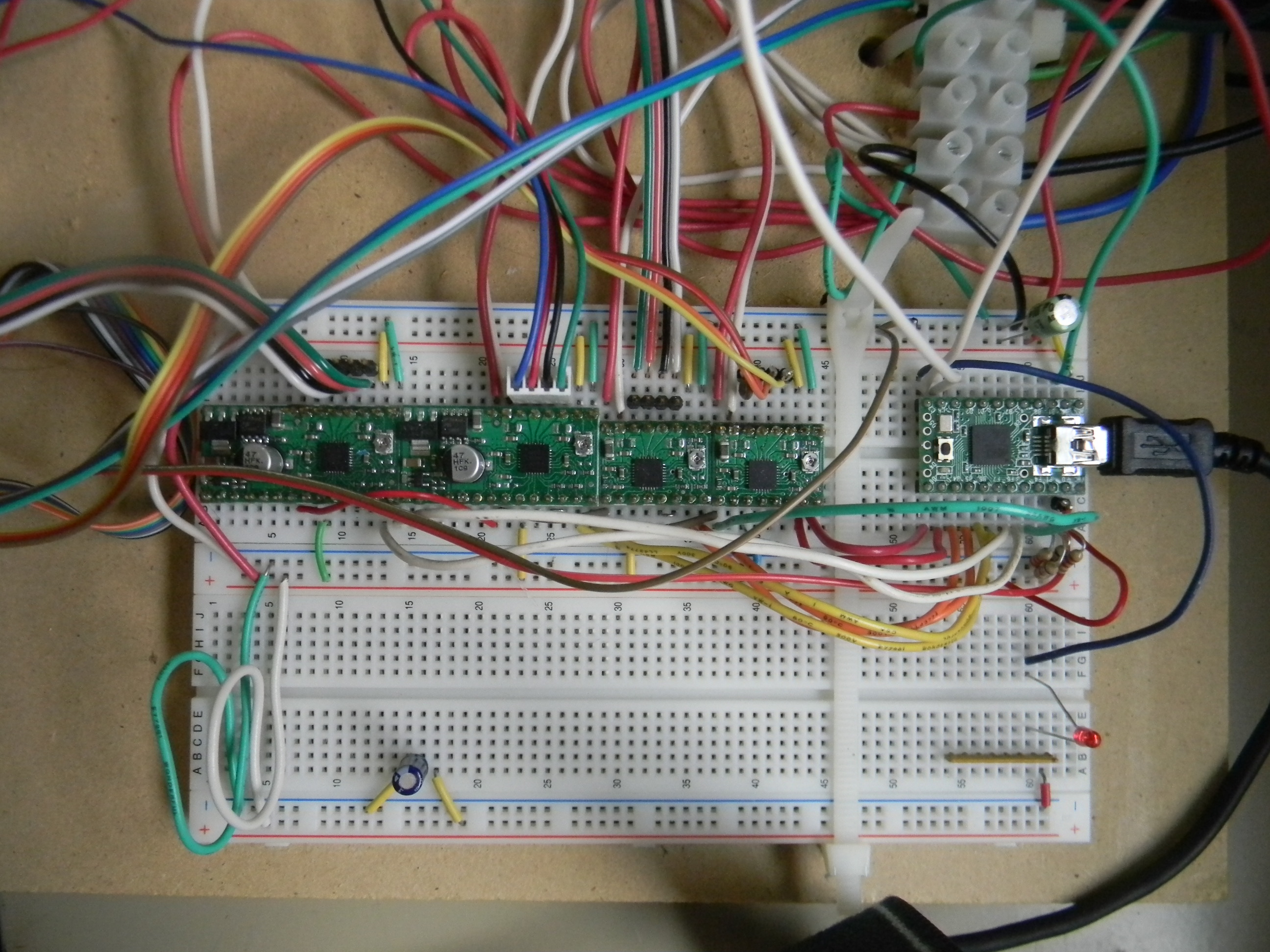
- I mounted the calibration resistor R2 in one row lined up with the appropriate Teensy pins: R2 vertical with short side in the +5 rail and long side in the first pinhole, leaving the third pinhole for the thermistor. Repeat for extruder and bed. See lower right corner of Media:TeensyBreadboard20121031.JPG at points (60-61) X (+,-,A,B) for a picture. If you have a 100K thermistor, you might not want to use a parallel R1.
- Check and test
Options
- The version shown above shows a Teensy 2.0, a couple Pololus with voltage regulators, a couple regular Pololus, a single heater output for the extruder, no endstops, and a single thermistor circuit. The Pololus are fed 12v through separate lines.
- The $24 Teensy 2.0++ uses an AT90USB1286, which matches the Teensylu and Printrboard chips, which may make compiling and configuring a firmware easier. It also has lots of extra IO pins.
- The Teensy 2.0 has 25 IO pins, 12 of them can do analog input, while 7 of them do PWM output, which is more than enough for the 15 pins required for 4 steppers, 2 heaters, 2 thermistors, and 3 endstops.
Discussion on first build
- 2012-09-29 -- The original thermistor circuit is pretty noisy, with successive dT up to ~10C. The thermistor is fed off of the +5 rail supplied by an ATX power supply, and uses a 4.7uf capacitor, small relative to other electronics. Using a regulated 5V supply and a 10uf capacitor as in Ramps#Schematic or Sanguinololu may help with the noise. Alternately, you could filter it in software as in https://github.com/triffid/Teacup_Firmware/blob/Gen7/temp.c#L292
- 2012-10-29 -- The teensy and 4 pololus would take only 12+4*8=44 columns on a breadboard, so it should fit easily on one slab of 830 point solderless breadboard.
- To avoid overloading the breadboard connector and busses (<2A), I use a 10A terminal strip connected to the powersupply, and run a separate 12V line to each Pololu Vmot input. For the extruder and the bed heaters, I wire the MOSFETs directly to the terminal strip and bring just the gate lines back to the breadboard. Nophead had a post about something like this at http://hydraraptor.blogspot.com/2012/07/sanguinololu-fan-hack.html
- 2012-10-29 -- The thermistor capacitor didn't seem to smooth the noise much. Maybe I should try to reduce the noise with a slower PWM frequency.
- 2012-11-04 -- If you are building this, I'd recommend trying the Teensy++ 2.0, which uses the AT90USB1286 and should be compatible with several standard firmwares. I've not tested it, but it should work with Marlin as MOTHERBOARD = 8 with the connections modified to match pins.h or vice versa. Under Sprinter it should be MOTHERBOARD = 8 or 9, with either pins.h or the connections modified to match. With Teacup it should work with MCU_TARGET = at90usb1287 in the Makefile, and a config.h modified apropriately.