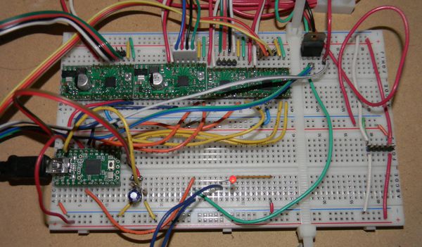
Teensy Breadboard
Teensy Breadboard
Combines a $16 ATmega32U4 based carrier from http://www.pjrc.com/teensy with Pololus on a solderless breadboard. Runs Teacup through integrated USB using LUFA serial at 38400 baud. (Teensy is capable of 12MBit/sec communication per [[1]]. Tested at 230400 baud with CoolTerm, and 250000 Baud with Pronterface with modified Teacup using Teensy's usb_serial* routines.) Possible upgrade path to the AT90USB1286 on a $24 Teensy++ towards Teensylu and Printrboard compatibility. Possible upgrade path to a 32 bit ARM Cortex-M4 48MHz processor on Teensy 3.0 (Was $22 on Kickstarter 2012-09-15).
Firmware
- Teacup/Gen7 branch: https://github.com/triffid/Teacup_Firmware/tree/Gen7 my modifications are in https://github.com/drf5n/Teacup_Firmware/tree/Gen7 Most of the modifications are in triffid's upstream Gen7 branch.
Pinout
My pinouts from https://github.com/triffid/Teacup_Firmware/blob/Gen7/config.teensy.h :
/*
	Machine Pin Definitions
	- make sure to avoid duplicate usage of a pin
	- comment out pins not in use, as this drops the corresponding code and makes operations faster

Teensy http://www.pjrc.com/teensy ATMega64U4 carrier:

DaveX plan for Wallace:
                               USB
           GND       GND |-----#####-----| +5V              ATX +5SB
     ATX PS_ON         0 |b0   #####   F0| 21 A0            Extruder TC
         X_MIN         1 |b1           f1| 20 A1            Bed TC
         Y_MIN         2 |b2  /=e6     f4| 19 A2            Stepper -ENABLE (or -SLEEP)
         Z_MIN         3 |b3 *      *  f5| 18 A3            STEP X
                 PWM   4 |b7  aref=/   f6| 17 A4            DIR X
                 PWM   5 |d0           f7| 16 A5            STEP Y
                       6 |d1           b6| 15 A6  PWM       DIR Y
                       7 |d2   V G R   b5| 14 A7            STEP Z
           Fan         8 |d3 d c n S d b4| 13 A8            DIR Z
      Bed Heat   PWM   9 |d6 5 c d T 4 d7| 12 A9  PWM       STEP E
 Extruder Heat   PWM  10 |d7 * * * * * d6| 11 A10 (led)     DIR E
                         --------------------
                          23 ^      \ \----22 A11
                                      \------ RST

      Interior E6: 24, AIN0, INT6
      Interior Aref : Aref
      End d5 : 23
      End d4 : 22, A1
With This configuration there remain 4 (or 7, if you count the three in the interior) IO pins leftover.
Options
- The version shown above shows a Teensy 2.0, a couple Pololus with voltage regulators, a couple regular Pololus, a single heater output for the extruder, no endstops, and a single thermistor circuit. The Pololus are fed 12v through separate lines.
- The $24 Teensy 2.0++ uses an AT90USB1286, which matches the Teensylu and Printrboard chips, which may make compiling and configuring a firmware easier. It also has lots of extra IO pins.
- The Teensy 2.0 has 25 IO pins, 12 of them can do analog input, while 7 of them do PWM output, which is more than enough for the 15 pins required for 4 steppers, 2 heaters, 2 thermistors, and 3 endstops.
Discussion on first build
- 2012-09-29The original thermistor circuit is pretty noisy, with successive dT up to ~10C. The thermistor is fed off of the +5 rail supplied by an ATX power supply, and uses a 4.7uf capacitor, small relative to other electronics. Using a regulated 5V supply and a 10uf capacitor as in Ramps#Schematic or Sanguinololu should help with the noise.
