Talk:RepRap Morgan extended BOM
Hi Robert,
I too want to build a morgan but have been waiting for Quentin's updated instructions. I'm tired of waiting. Seeing stellar work like yours makes we want to build. The group in Charleston has put together some good material.
Interested in your work on the 12-z_bracket. Somehow, I have two of the z-brackets with the tear drop cutouts, one with a triangular back-plane structure, like in current github/stl for morgan, the other like yours with only the single back-plane.
Also, interested in your use if the steel drive shafts. Where did you get your 15mm and 22mm pipe?
Thanks.
Steve
- Hello Steve,
- glad to see my work being appreciated. I found the steel tubes in our local DIY market.
- Both have a wall thickness of 1mm and are very smooth and strong and they were less expensive than in copper. You should pay less than 1,50€/m.
- Maybe standard steel-c-pipes (they have 1,5mm walls) would do it too. You'll find a lot of these at ebay below 2€/m.
info on captive nuts
Hi there,
Been waiting for response from Quentin for several days. Was talking with him about the drive shaft assembly, he described the nuts pressed into the sides of the 15mm pipe. Anyway, I responded back asking how far from the ends do the captive nuts get pressed into the pipe? and which end of the pipe goes on the threaded rod-do the captive nuts lead or follow, presuming their at one end. That's the question I've been waiting for an answer.
No response - very odd, historically he has responded very quickly. I know he's frustrated his instructions haven't been released.
So, I thought I'd reach out. If you can't help, I am going to the Charleston Makelab and ask angrychisel his opinion. Really wish I had better instructions. Have you made notes you can share? Thanks.
Steve
- Hello Steve,
- You should get the student version of Autodesk Inventor (it's free for students though). With that you can look at my virtual Morgan in every detail you need.
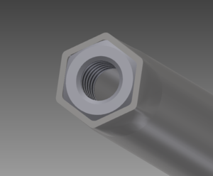
- The story with the 15mm pipe goes like this: On each end you press an M8 nut up to 80% of its height into the pipe. This bends the ends of the pipe into the M8-shape (you can see that demonstrated in the extended BOM in the "Hardware"-part). So when you screw the pipe onto the threaded rod (with M8 nuts inserted in both ends) the shaped ends of the pipe hold the M8 nuts and it acts like a very long nut itself. Quentin uses this technique to stabilize the threaded rod so that it doesn't bend while printing (the threaded rod alone is not strong enough over long distances).
- To press the M8 nuts into the pipe you screw an M8 nut on an M8 bolt. Then you insert the bot into one end of the pipe until the nut stops the insertion. Then you can press the M8 nut further into the pipe by knocking the M8 bolt into the pipe with a hammer.
- With a copper-pipe this is quite easy and doesn't need much force. With a steel-pipe you should support the M8-shaping of the pipe by using a vice on the pipe-end with the M8 nut in it. It is not necessary, that the nuts fit absolutely perfect, because they will stay firm once the pipe is screwed onto the threaded rod.
- The direction of the pipe doesn't matter, because its symmetrically.
- My virtual Morgan as a basis I want to make some small animated videos as assembly instructions. Or maybe someone is so kind to help me with that. It's a lot of work. But the model is there and realistic in every detail.
- If you need more tips, feel free to ask.
- About Quentin: I guess he just lost overview about all the questions in the forum. He is still answering fast, as far as I can see it. Maybe he just forgot some older questions, because he's quite busy I think.
- Greetings
- --RobertKuhlmann 20:22, 4 September 2013 (UTC)
re-peat captive nuts
Hi Robert,
I must be just thick-headed. You gave a detailed response. Mostly made sense. Thank you.
The problem I have is I keep expecting to see nuts pressed into the sides of the 15mm pipe.
Every image shows nuts on the threaded rod, only.
Quentin did get back with me. I responded to his 'Lillian' post and asked again. His answer made me a little confident. "Press the nuts in the sides near the end of the pipe." Again, never seen an image. Likewise, don't understand their use being horizontal to the vertical threaded rod. Never see ref to inserting a bolt across the pipe into the captive nuts..
I got my drivewheel hole widened to fit my 3/4" copper. So, I may be on the cusp. I didn't get an email when you updated this-I'll keep an eye open.
Thanks.
Steve
- Hello Steve,
- do you mean you missed a picture like this one?
- The pipe has a nut on each end. This is to stabilize the threaded rod, so that it doesn't bend while printing. The threaded rod alone would be able to twist and bend a bit over its length. With the steelpipe around it, fixed by the two nuts, this doesn't happen.
Hi (Not sure about this editing) No - not at all. The image I'm expecting has the nuts pressed into the sidewalls of the pipe.
- Hm. Why should you? The nuts are pressed into the pipe on each side/end. They are not pressed into any wall or into the wall of the pipe. That wouldn't make any sense.
- I think you just didn't get Quentin right. He means it in the exact configuration I showed to you.
- Regards
- Robert


