Stepper Motor Controller Card v1.2
Stepper Motor Controller Card - v1.2
<div class="thumb tright"></div>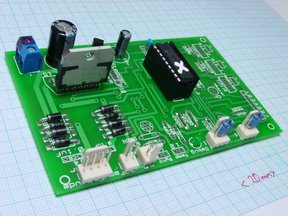
Prerequisites
This board is a modified Universal Controller Board v1.2. as shown on the right. Build that first, then follow the steps here.
Make it!

There is very little work needed to take a universal controller board with all the common components and to turn it into a stepper controller. All you need to do is to add the following components, which are shown in the magnified part of the picture:
| Component | Value |
| P3 | 2 pin connector |
| R10 | 4K7 ohm resistor |
| R11 | 4K7 ohm resistor |
These form the synchronization link between the stepper control boards.
In addition, the stepper motor connector (P9, top right of the picture) has two capacitors (C5 and C6) beside it for an extruder controller. These are not needed for a stepper controller, but you should put dabs of solder over the holes where they would have connected on the reverse of the board. This is because those connections have to carry a high current, and the drilled holes increase their resistance slightly.
Bolt a heatsink to the L298N (U2). Any heatsink that will handle about 10oC per watt or better will do. Put a little thermally-conducting silicone grease between the chip tab and the heatsink before you tighten it up.
For details of the stepper motors RepRap uses follow this link.
There are three of these boards for the X, Y, and Z stepper motors respectively. Label them X, Y, and Z with a felt-tipped pen so you don't forget which will be which.
Program It!
Now that your board is complete, you will need to program it.
If you are not familiar with programming firmware, please see our guide on programming a PIC.
For each board, program a 16F628 chip with the appropriate firmware file. The following table lists which firmware to use on each board:
| Firmware File | Axis |
| stepmotor.hex | X |
| stepmotorb.hex | Y |
| stepmotorc.hex | Z |
The programs in each are identical exept for one number - the address of the corresponding PIC in the token ring.
It's also convenient to label the PICs. I find that the best way to do this is to put a dab of typewriter correction fluid on each one, then to write X, Y, or Z on that when it's dry. (Mystery: there's hardly a typewriter left on the planet; so how is it that everywhere still has typewriter correction fluid?)
Alternatively, you can buy small stickers at an office supply store, write on that, and then stick it on the chip. Regardless of the method you use, its important to label the chip so you know which board is which.
The boards are now ready for attaching to your RepRap machine. Put them aside and commence to building the actual machine.