Stepper Expander
Release status: working
| Description | For when you need more stepper drivers on your printer.
|
| License | |
| Author | |
| Contributors | |
| Based-on | |
| Categories | |
| CAD Models | |
| External Link |
Contents
Intro
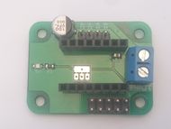
The Stepper Expander X1/2/3 is designed as an easy way to add more stepper drivers to your 3D printer and other electronics.
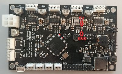
It can also be used to repair / patch-up boards where the stepper driver chip is SMD soldered on the board like Melzi, Printrboard and so on....
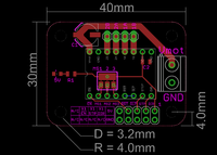
Stepper Expander X1
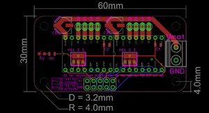
Stepper Expander X2
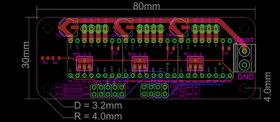
Stepper Expander X3
Pinout
| X1 | X2 | X3 | ||||||||||||||||||
|
|
Notice: the very first production batch, identified by green PCB (as opposed to the newer black version) counter-intuitively has the text VMOT placed next to the negative power terminal. This is fixed in newer batches as the VMOT label has been moved next to the positive side of the screw terminal.
As An Expansion Board
Using RAMPS
See Adding more extruders for an easy guide to adding a third extruder motor to RAMPS
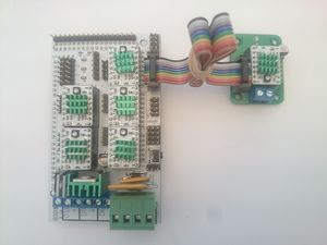
RAMPS capable of running 3 extruder motors.
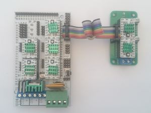
RAMPS capable of running 4 extruder motors
Repair Jobs
There are many different 3D printer control boards and variations thereof but the general steps are the same.
PrintrBoard
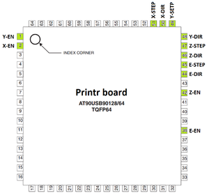
Identify the contact points for DIR, STEP and ENABLE.
As the traces can vary from one board version to another it's recommended to make the connections directly to the MCU unless there are other obvious alternatives.
The 5V and GND are usually easy to find at the capacitors.
Cut the signal traces to the defective stepper driver so it won't make any trouble in the future.
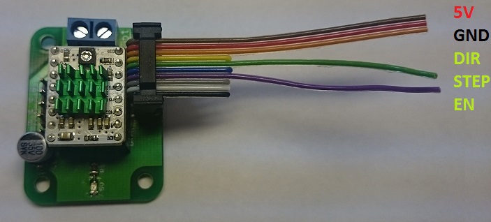
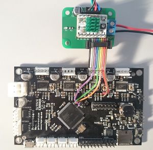
Take a 10 wire ribbon cable with a 2X5 female pin header connector and cut it to your desired length.
For the Stepper Expander X1 only wire's 1, 2, 3, 5 and 7 are used.
Wire 1 = 5V
Wire 2 = GND
wire 3 = DIR
Wire 5 = STEP
Wire 7 = EN
Solder the wires to the right connections.
It's a good idea to secure the wires to the board with hotglue or similar to prevent them from breaking off due to vibrations.
Connect the stepper motor to the Stepper Expander and the power terminals on the Stepper Expander to the main board's power input and you should be good to go.
Melzi

First remove any components that are causing any problems from the stepper driver you want to replace.
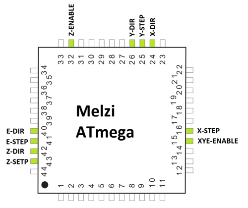
Identify the contact points for DIR, STEP and ENABLE.
As the traces can vary from one board version to another it's recommended to make the connections directly to the MCU unless there are other obvious alternatives.
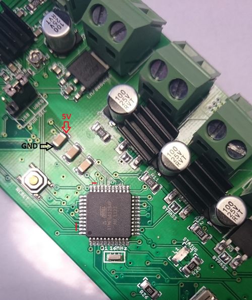
The 5V and GND are usually easy to find at the capacitors.
Cut the signal traces to the defective stepper driver so it won't make any trouble in the future.

Take a 10 wire ribbon cable with a 2X5 female pin header connector and cut it to your desired length.
For the Stepper Expander X1 only wire's 1, 2, 3, 5 and 7 are used.
Wire 1 = 5V
Wire 2 = GND
wire 3 = DIR
Wire 5 = STEP
Wire 7 = EN
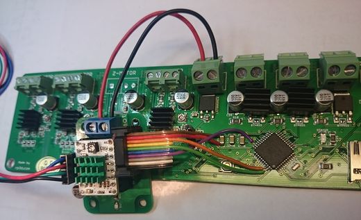
Solder the wires to the right connections.
It's a good idea to secure the wires to the board with hotglue or similar to prevent them from breaking off due to vibrations.
Connect the stepper motor to the Stepper Expander and the power terminals on the Stepper Expander to the main board's power input and you should be good to go.
