SeeMeCNC
Release status: working
| Description | |
| License | unknown
|
| Author | |
| Contributors | |
| Based-on | |
| Categories | |
| CAD Models | soon to be @ http://seemecnc.org
|
| External Link |
Contents
Introduction
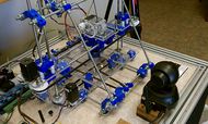
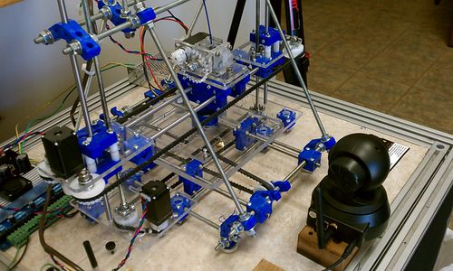
SeeMeCNC H-1 design is based on the Huxley. Primarily to produce as many parts as possible with injection molded parts.
Notable difference in the H-1 is that it's built primarily for using standard SAE hardware and English units. All of this is supposed to make the sourcing parts and building components easier in the U.S.A.
Uses 1/4-20 threaded rods for the main frame and the Z axis lead screw, and NEMA 11 thru 17 sized Stepper Motors.
H-1 Build Instructions
http://seemecnc.org soon
http://seemecnc.com/assembly/ for assembly drawings
Supplies
All of the hardware should be readily available at local hardware stores. The plastic parts can be purchased from SeeMeCNC.com or from someone who has printed the parts from the CAD files.
Some parts, like the PTFE tubing and electronics, have come from sources other than local stores.
(soon to be uploaded)
Dimensions
Approximate Build envelope is 6" X 7" X 4". Although, enlarging the machine slightly involves only replacing the threaded rod sections
Injection Molded Parts
SeeMeCNC.com makes their own tooling and injection molds their own parts, through their company Partdaddy.com
Printed parts
Need sources for printed parts
Electronics
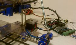
SeeMeCNC is using mach3/EMC2 configurations on their prototype machines. Any other type controller electronics could work, such as arduino, sanguinolulu, ultimaker RAMPS etc...
Do not buy their electronics if you want to run an arduino based setup, just buy their hardware.
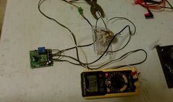
Note from John's testing on 12/27/11-when building the Ramsey(Velleman MK138) Temp Control Kit, replace R5 with an 18K resistor. This will allow the temp control to work up to about 480 degrees.
Steppers
Standard NEMA 11 OR NEMA17 steppers.
Extruder
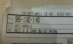
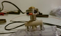
"Steve's Extruder" is a gear-driven, dual driven pinch feed roller design. It uses either a NEMA 11 or NEMA 17 stepper motor. The hot-end uses two 6.8 Ohm resistors, and a 100K ohm thermistor for temperature control. The gear driven unit has a gear reduction ratio of appx. 6.5:1.
Timing belt
Timing Belts are XL, in 1/4" width.
X = 25-3/4" length, secured to rear of extruder carriage bearing blocks
Y = 41" length, secured to bottom of table
Z = 310XL closed loop (31" length)
Bearings
The linear axis rollers use (stock) (32) Plastic Acetal molded bearings, or (custom) (32) R2ZZ (1/8ID x 3/8OD x .156W) ball bearings.
"Steve's Extruder" Uses (4) R4ZZ? 5/8" x 1/4" bearings
Z axis support plates use (2) R4ZZ? 5/8" X 1/4" bearings
Nuts and bolts
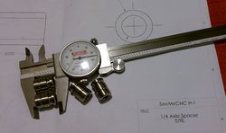
All hardware is standard inch units. 1/4-20 Threaded Rod 1/4 Drill Rod (for linear rod) 5-40 nuts/bolts for sub assembly of linear bearing plates The only hardware that is not a standard SAE size is the bolts for the steppers, which are 2.5 or 3 x .5 mm
To bend the 4 threaded rods(thanks, Yoyo): 1) Draw two lines on legal paper 3" apart. 2) Draw a 8.5" line connecting them 3) Take 9 nuts and screw them to the bottom of the threaded rod, all nuts abut each other and the last nut is flush with the end. 4) Take the 7/16" spanner, the same one you use for the other nuts and slide it about 1/4" above the top most nut. 5) Apply elbow grease and bend the rod until the angle matches that of the paper guide. 6) Repeat until done.
Ongoing development
Yahoo Groups page, compliments of Andy
