Sarrus Z Linkage
This page is a development stub. Please enhance this page by adding information, cad files, nice big images, and well structured data!
Release status: unknown

| Description | documenting a generic tool/artpiece
|
| License | |
| Author | |
| Contributors | |
| Based-on | |
| Categories | |
| CAD Models | |
| External Link |
This page represents an example development page and showcases many features that can be used in creating new development pages.
Contents
Forum thread?
http://dev.forums.reprap.org/read.php?166,37225
Build notes
Print one each of the end plates. Print 4 of plate_a and 4 of plate_b. These have an overhang, but using the 'support on exterior only' setting on Skeinforge gives workable results. Also, teh plate_ab_merged file allows you to print the hinge plates in pairs.
Drill out all the small holes with a 1/16" drill bit, then use 1/16" brass rod to make hinge pins.
Text (Motivation)
I am exploring the Sarrus linkage. I think that it has the potential to make mostly printable linear bearings.
This is an attempt at making a Z axis that would be suitable for lifting a platform on which to print, or maybe holding an extruder from above.
It is a continuation of a series of attempts to use simple hinges to make complicated things.
I have named it the rather uninspired name of Z01 because it is just one part of a much bigger story, I hope. When I have a Sarrus based printer, I will probably name it Sarrus, to honor mathematician who came up with the fundamental geometry and to continue the reprap tradition of naming machines after people from the 19th century.
More Descriptive Text
Features:
Intended to be printable on a Makerbot Cupcake (but I have not done it).
Total range of motion 102 mm.
Hole for mounting skate bearing (608).
Room for 10-32 or similar threaded rod
Mounting hole for 10-32 nut.
Flexure for allowing sideways shifts of 10-32 nut.
Performance evaluation:
The Z01 is not stiff to rotation of the end pieces. If you hold one end and push sideways (at a right angle to the axis of motion), that end moves and rotates. This is because the hinge plates twist slightly. It is not due to hinge looseness. Inperfections in the drive rod (10-32) like bends and bearing imperfections push it in just that way. I do not think that this is stiff enough for a 3D printer Z axis.
I designed this with Art Of Illusion 2.7.
Files and Parts
Sub Assemblies and Related
none.
Downloads
Photos and Drawings
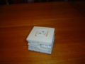
Model Z01 in closed state
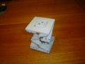
Model Z01 in halfway state
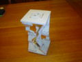
Model Z01 in fully open state


More Examples
Entrepreneurship (Kits, Paypal)
None.