Sanguish
Release status: experimental
| Description | All in one electronics with Toshiba drivers
|
| License | [GPL]
|
| Author | |
| Contributors | |
| Based-on | |
| Categories | |
| CAD Models | |
| External Link | (none)
|
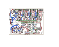
Sanguish is an all-in-one electronics platform similar to Gen7 and Sanguinololu. The main difference is that Sanguish is using the through hole Toshiba TB6560AHQ drivers in place of the Pololu driver daughter boards. The main advantage is cost savings, as the Toshiba drivers are much less expensive than the Pololu boards. In addition it is likely that the Toshiba drivers will allow higher current motors to be used. The HZip form factor will be much easier to heat-sink, and the drivers will handle more current before requiring a heat sink than the Pololu drivers will.
Note: The enable line is inverted from the way it works on the Pololu drivers so this MUST be changed in firmware before powering on the 12V to the drivers, otherwise the smoke will escape.
Contents
How to get it
Alpha Board:
Dec 2012 The board has passed the initial movement tests, but is not quite ready for prime time.
Known issues with alpha board:
The relay is wired incorrectly
The power control pin may need to be moved to correct an as yet unexplained toggling of the relay.
Beta board:
3-1-2013 Just finished the beta board for the board houses. It's probably still pretty rough but I expect that it will perform fairly well.
Changes from alpha:
The relay wiring is fixed.
The layout is now under 10 cm X 10 cm so it can be made very cheaply at seeedstudio or iteadstudio
The power toggle issue comes from the sanguino bootloader which toggles PB0 on reset. This issue can be fixed by using the Gen7 bootloader. Perhaps in future revisions the power pin can be moved to an inactive pin to allow flexibility to use either bootloader.
Files: I'll upload soon when I have time.
PCBs
Alpha board has passed initial tests after repair of the relay routing.
Components
Here is the preliminary Mouser project. Mouser project
It should have everything in it needed to build the basic board. No external parts are included. So cabling, end-stops, etc. are left to the user to source. You can of course use the Gen7_Endstop_1.3.1 or use mechanical end-stops. The mouser project is still pretty rough as the parts list is a bit fluid at the moment.
Cost
The mouser project with all needed components comes to $49 in QTY 1 and $404 in QTY 10. In order to bring down the total cost I substituted the pin and socket headers, capacitors and screw terminals from Tayda electronics. This brings the total to
Mouser components = $260.97 + S+H (est $12) = $272.97
Tayda components = 21.20 + S+H 5.99 = $27.19
PCB Seeedstudio Fusion PCB 10x10 cm = $24.90 + S+H $7.79 = $32.69
Total = $332.85
Got the board under 10x10 cm which brings the board cost way down. Now I'm down to $35 per kit(qty 10)! I just ordered two batches for beta testing, one from seeedstudio.com and one from iteadstudio.com, so I'll be able to compare the two services.
Parts List
Electronic Components
| Description | Part Number | Quantity | Comments
|
|---|---|---|---|
| 560 Ohm resistor | 0 | 5 | LED and Transistor bias |
| 4.7 KOhm resistor | 0 | 3 | Temp and reset |
| 0.5 Ohm 1/2 W resistor | 0 | 16 | Current sense resistors |
| 40 pin female header | 0 | 3 | Sockets for driver chips |
| 40 pin male header | 0 | 3 | jumper headers, connectors etc. |
| 10 A Relay | 0 | 1 | Power on sequencing switch |
| 40 Pin Dip socket | 0 | 1 | Socket for Atmega |
| ATMega | 0 | 1 | |
| Crystal | 0 | 1 | 16 or 20 MHz |
| 22 pf Capacitor | 0 | 2 | for crystal oscillator |
| NO Push button switch | 0 | 1 | Reset Switch |
| 0.1 uf ceramic capacitor | 0 | 13 | various |
| 10 uf electrolytic capacitor | 0 | 6 | driver isolation and temp |
| 100 uf electrolytic capacitor | 0 | 3 | power input caps |
| Toshiba TB6560AHQ drivers | 0 | 4 | drivers |
| FET | 0 | 3 | heaters and relay driver |
| LED | 0 | 2 | heater indicators |
| 2 pos screw terminal | 0 | 4 | power in and heater out |
| 100 pf ceramic capacitor | 0 | 4 | driver clock capacitors |
Initial build
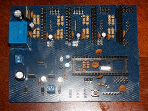
The initial build is done and ready for testing. Here is a picture of the board ready for atmega and drivers. The initial board was made using toner transfer on single sided copper clad. This design is not optimal for single sided manufacture and lots of jumpers will be required to complete the board. If it performs as expected all future boards will be manufactured double sided boards. As you can see the drivers and atmega are socket-ed for easy replacement as these are the components that most often get damaged and need replacement.
Update: 2-25-2013 Initial testing is complete with with a few initial issues, but overall the tests are going well.

