RepRapOneDarwinThermoplastExtruder
Contents
The Thermoplast Extruder
Table of contents
Introduction
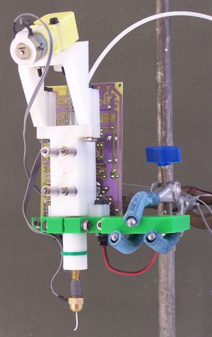
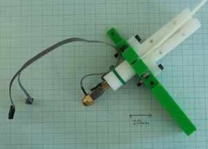
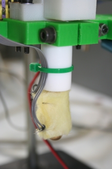
The thermoplast extruder is the central part of the RepRap machine. It takes a 3mm diameter filament of a polymer (usually polycaprolactone; the white loop coming into the picture from top right), forces it down a heated barrel, and then extrudes it as a melt out of a fine nozzle. The resulting thin stream is laid down in layers to form the parts that RepRap makes. The thermoplast extruder is shown here held in a retort stand undergoing tests and calibration.
(There is no significance to the green-coloured clamp-part shown - we were just trying out a different coloured polymer.)
What order do I do things?
Obviously you'll need all the parts and components first; the bill of materials is linked just there and below.
Start with the Extruder Controller Board, which you should have already made and tested if you have followed the order on the Main Construction Page. You'll need this to test and to use the finished extruder.
Next the mechanical parts need to be made.
Then make the motor drive assembly, then the polymer guide.
Finally assemble the entire machine, test it, and calibrate it.
Safety
%RED%OBVIOUS WARNING: the heated nozzle gets very hot (almost as hot as a soldering iron). It is a bad idea to touch it or the wires leading to it when the machine is working or has just recently been switched off.
LESS OBVIOUS WARNING: The motor is geared down to drive the screw-thread very slowly. This means that, even though it is a fairly weedy motor, it is turned with a considerable torque. It is well-nigh impossible to get one's fingers in the works, but if one manages to do so, the motor will just keep going and injuries will occur.
WARNING FOR NON-CHEMISTS: The nozzle is partially made from PTFE. PTFE is stable up to 250 oC. Above that it breaks down into various gasses, some of which are quite toxic. The extruder should not be operated above 250 oC.%ENDCOLOR%
Bill of Materials
The bill of materials is on a separate page to allow you to flip quickly between it and this one. Open this link in a new browser window or tab to see it.
Extruder Controller Board
Take the Extruder Controller Board from the place where you stored it after you'd made and tested it.
Non-rapid-prototyped mechanical parts
The construction of the non-rapid-prototyped mechanical parts for the extruder is described on a separate page here. Make those next.
The motor drive assembly
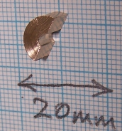
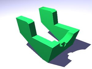
Start by taking the two half-round brass bearings for the screw drive and inserting these into the slots in the screw holder. They are deliberately tight, and this can be a bit tricky. The easiest way is to put them in at an angle, then to force the upper edge flat by pushing it with a screwdriver. It doesn't matter if the top face is not entirely flat; as long as the bearings are properly bedded in the central half-holes will still be axially aligned.
Next attach the drive motor to the angled motor holder using two 35mm M3 cap screws, two nuts, and four washers. You may need to run a 3mm drill down the mounting holes in the motor first - these are nominally 3mm in diameter, but are sometimes a little undersized. Don't skimp on the washers - you're bearing steel on plastic and you need to spread the load and to minimize wear.
Attach the angled motor holder to the screw holder using two 35mm M3 cap screws, two nuts, and four washers.
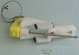
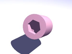
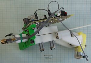
Fit the nut on the end of the drive screw into the hex drive (it should be tight, but not stiff) and fit that to the motor - the result should look like the photograph. Check that when you bend the wire the bearing lands on the screw drive match up with the brass half-round bearings.
Put a little lubricating grease on the bearings. If you add too much, excess will get dragged down by the polymer you are using and mixed in the melt...
Finally, solder a 210mm length of fine two-way ribbon cable to the motor (insulate the terminals with heat shrink), and put a 2.54mm two-way connector socket on the end.
The polymer guide
Cut a 500mm length of the 3mm diameter polymer filament that you will be extruding (usually polycaprolactone). Offer it up to the side of the barrel assembly such that its end is at the same depth as the end of the dome nut nozzle. Mark where the top edge of the PTFE comes on it using a felt-tip pen.
Push the PTFE part of the extruder barrel into the hole for it in the clamp. Align it so that it is exactly flush with the top surface.
Clamp it with the 30mm M4 cap screw, nut, and two washers. This needs to be done up tight, but don't go crazy - you'll split the clamp.
Push the filament down the barrel to the end, so it rests on the inside of the dome nut. The mark you made should tell you when you've got there. The filament should slide stiffly but smoothly; there may be a slight extra resistance as the end passes the join between the PTFE and the brass barrel.
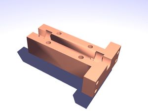
Loosely attach the polymer holder to the clamp using four 25mm M3 cap screws, four nuts and eight washers. Adjust the sideways position of the polymer holder in the slots in the clamp so that the polymer filament is centrally aligned with the channel in the polymer holder. Tighten the screws and nuts.
Assembling the extruder
Cut four 13mm lengths from the 3mm internal-diameter stiff silicone tube using a sharp blade. Take care to get the ends square.
Thread four M4 nuts onto the ends of the four 55mm lengths of M3 studding. Put washers inside them and push them through the four holes in the main body of the polymer guide so the nuts end up on the outside face (that is, the face without the channel).
Put the motor and screw assembly onto the four studding lengths, taking care that the drive screw is aligned with, and sitting in, its bearings (prod it with a small screwdriver...).
Holding the assembly together with one hand, put four washers onto the studding, followed by the four lengths of silicone tube, four more washers, and four more nuts. Do the assembly up loosely so that it is held, but is not tight. The silicone tubes form springs that give the extruder a certain compliance against slight variations in filament diameter as it passes through.
Cut four 5mm lengths from the 3mm internal-diameter silicone tube.
Place these lengths on the short projecting ends of the 3mm studding where the printed circuit will go. They are to prevent the ends of the threads touching the circuitry - check that they don't protrude so far that they might.
Attach the circuit using the M3 15mm cap screw and a 35mm one. Put washers and nuts on the ends that projects through the clamp, but do not put washers on the PCB end (it might cause shorts). Attaching the PCB should retain the short silicone tube separators in place against the PCB. You may have to move things slightly to get this neat, as the soldered projecting wires on the back of the PCB sometimes catch on the silicone. This arrangement seems a little insecure. Don't worry - it is only temporary for testing; ultimately the PCB will be mounted on the moving carriage, not the extruder itself.
Finally, wrap a little fire-proof heat insulation round the nozzle. The glass-fibre wool that is used for building insulation works well (sneak into the attic with a pair of scissors when nobody's watching...). Secure it with a couple of twists of bare wire.
Testing
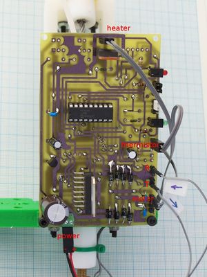
Plug the heater connector into the 2-pin connector P4 (next to the TIP110 power darlington), the thermistor into the 2-pin connector P2 (beside the main LED), and the motor into pins 1 and 2 of P9 (the four-pin connector in one corner of the board - you want the two pins nearest the board's centre).
The heater and thermistor do not have any polarity and can be plugged in either way round. You are about to test if you have the motor connected the correct way.
Mount the extruder vertically in something that will hold it securely with the nozzle about 100 mm above the workbench; I use a chemistry-lab retort stand and clamp (see the first picture above).
Connect an RS232 cable between your computer and the Comms/power board. Connect transmit on the Comms board to receive on your new board, and receive on the Comms board to transmit on your new board. Take particular care to get the power connections right - the wrong polarity will do a great deal of damage.
Open the Eclipse Java development program. Open the Reprap project, and walk down the tree: src -> org.reprap. Right-mouse click on main.java and go down to Run as... -> Java Application.
Select Preferences from the File menu and set the port to the one your RS232 cable is connected to.
Click on the Extruders tab. Set the beta value to that for your thermistor (3480 if you use the standard thermistor) and the value of Rz to the resistance that your thermistor has at 0oC [29000 (29K) for the standard one].
Click on the Axes tab and select Cartesian as the geometry.
Click on OK in the Preferences box.
Check that the four long M3 studding lengths that hold the two halves of the extruder together have not been tightened - they should be slightly slack.
Turn on the power.
Now, from the Tools menu select Extruder exerciser. This should open a window that looks like this:
The Feedstock Empty box will be checked if you have a jumper on K1.
Drag the extrude speed slider to the extreme left. Click on the Extrude button.
Drag the extrude speed slider slowly to the right until the motor just starts to rotate. Check that it is rotating the correct way (anticlockwise when viewed from on top of the extruder).
Click the Extrude button again to turn the motor off.
Turn off the power and close the extruder exerciser window. (You may have to use the Eclipse red "kill process" button to do this.)
If the motor was turning the wrong way, swap the plug round where it is connected to the printed circuit board.
Tighten the four M3 studding nuts to force the two halves of the device together, clamping the polymer filament hard against the screw drive. Do this by hand - the right torque on the nuts is about as much as your fingers can generate on their own.
Check that the four lengths of studding projecting out the back towards the PCB are not touching it and are still held away by the short lengths of silicone tube.
Turn on the power, then run the extruder exerciser program again.
Check the Heater Active box. Enter a Desired temperature of about 30oC above the Current temperature and press "Enter". The heater LED should flash. This flashing is the heater coming on and off using pulse-width modulation to set its power. Be particularly careful not to type extra zeros by accident; otherwise when you press "Enter" the heater will come on full blast...
After a little while the Current temperature value should start to rise.
Allow the device to heat up slowly, gradually increasing the Desired temperature in 10o increments as the Current temperature approaches the value set. If you are using poycaprolactone take it up to about 80oC.
Drag the motor speed slider to the extreme left.
Click the Extrude button to turn the motor on. Drag the speed control to the right until the motor starts to rotate. It will probably need a higher setting than before, as you have tightened everything and so more torque is required.
After a few seconds (the melt has to fill the nozzle nut) the polymer should start to extrude from the nozzle.
Experiment a bit with temperatures and speeds, but don't ask the motor to go too fast or you will damage it. When you select Extrude the software prints the extrude speed being used to the console (a number between 0 and 255). Note down the value that will just cause the motor to start turning from a standing start, and the value that gives a rate of filament extrusion of about 4mm per second out of the nozzle.
Close the window and turn everything off.
Calibration
This will take you about half an hour. You will need a pencil and paper, or a spreadsheet open in another window on your computer.
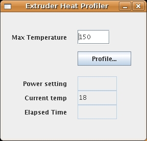
Make sure the extruder has completely cooled to room temperature. Then turn on the power and run the extruder heat profiler option from the tools menu. This will open a window like the one on the right. Set the maximum temperature in the top window to 150 oC. Wait for the Current temp value to settle, then click the Profile button.
The program will set the power level in the extruder heater, wait for its temperature to stabilize, and then print that temperature and the corresponding power level (a number between 0 and 255) to the console. It will then increase the power and do the same again.
Write down a table of the power levels and the temperatures, or type them in as adjacent columns in the spreadsheet.
Plot a graph of the results, and get the spreadsheet to fit a straight line through them (linear regression). That line will have the form:
temp = hmpower + hb
Where temp is the temperature in oC, power is the power value (0...255), hm is the gradient of the line, and hb is the intercept on the temperature axis. The line is the heater's power/temperature relationship (which will depend on many individual things, like how much insulation you added), and the software needs to know what that is to control the heater properly.
Stop the calibration program, open Preferences from the File menu, and select the Extruders tab. Enter the values of hm and hb, then select OK.
Shut down all the programs and turn everything off.
History
The Darwin extruder is a variation of the RepRap Mk II Extruder designed by Adrian Bowyer from an original idea by Vik Olliver. See that link for details.
-- Main.AdrianBowyer - 06 May 2007
