Rap@Home
Release status: unknown
| Description | Documentation of progress and resources related to Rap@Home project
|
| License | |
| Author | |
| Contributors | |
| Based-on | |
| Categories | |
| CAD Models | |
| External Link |
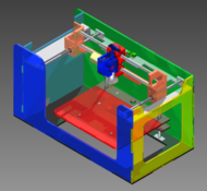
The Rap@Home is a 3D printer which is being developed for a high school engineering capstone course. Its development must follow the formal design process, along with any other criteria which we (3 high schoolers) choose to work under. The finished product will be given to the tech department for educational use; ideally, more printers will be made available to other schools in the district. This project is currently in the design stage; the paperwork, research, and preliminary design steps have largely been completed.
This page is under development; this project will be completed in July of 2011.
Contents
Overview
The process which me must use roughly resembles the following:
- History - Past solutions to related problems
- Interviews & surveys - Wants and opinions of potential customers
- Voice of the customer - Rank customer needs and wants from survey's
- Product Requirements - How the customer wants will be satisfied
- Research Past Solutions - How has this project been completed in the past, and how have related projects succeeded
- Solution - Brainstorm and think of own solution
- Design Stage - CAD the solution
- Prototyping and Testing - Test final design
Justification/Sales Pitch
The formal justification for the project was that home manufacturing could solve many issues related to sustainability, shipping costs, availability of parts, and other nice juicy problems to tackle. We placed some emphasis on a developing African village scenario, where A) small, simple solids could have high value and B) suppliers are not likely to ship. On the consumerist side, we likened it to the PC in the 70's- a bunch of basement geeks are exploring a technology which will have an important place in the future. For this reason, it's a pretty nice investment for a school district to make.
We also took a quick look at why a school would need a printer. We asked a few department heads the following questions: whether or not a 3D printer is worth $500, whether or not they could use it in class, and if they could think of any specific examples of how it could be used. First stop was the tech department; suffice it to say that there was no shortage of uses or support. Next was the art department; the teacher we talked to was intrigued by the possiblity of translating motion into a solid object. Anyone have a good idea on how to accomplish that?. In her opinion, $500 is a small sum to fund this project. The head of the Math department, thought that he could use the printer on rare occasions, for example the end of the year projects where models of entities such as hypercubes are needed. In his opinion, $500 is only worth it if the printer was shared by the school; he would not buy one specifically for the math department (fine by us).
Research Stage
If you're on this forum, I imagine you must know a little bit about the history of 3D printing. If not, keep looking around; you won't be looking long.
Existing Solutions
Our research plan was to identify the technology behind 3D printing so as to familiarize ourselves, then to compare the different qualities of the Fab@Home, RepRap, and MakerBot (having previously identified these as the best options). The metrics for comparison were (amongst other things) price, size, resolution, profile, and software. It was decided that MakerBot and RepRap use the best (cheapest and most flexible) control system, while Fab@Home has superior user-friendliness (in hardware and software) as well as a hot-swappable tool head that accepts syringe, cutters, plastic tools, etc.
At this stage, "existing solutions" is very high-level; although we did spend plenty of time looking at projects like the Pirated CupCake, that type of research didn't come until later.
Consult the Experts
Since we're located in Ithaca, we took a trip up to Cornell to meet Jeffery Lipton, who gave us a tour of the Fab@Home lab and explained the technology, software, and ideas behind their printer. In the end, we realized that all printers aren't so different from each other; "Fab@Home" isn't so much a 3D printer as it is a "standard." Their ultimate goal (and ours as well) is to bring 3D printing into the home in much the same way PC's are: with interchangeable parts and a diverse marketplace.
Conclusion
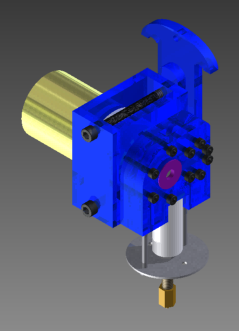
Our final decision was to combine the RepRap control system with a Fab@Home-based Cartesian bot and tool carriage. Although it runs on a Sanguino, it will be able to accept any tools Cornell has on hand and (hopefully) work with Fab@Home's own software. We will adapt existing Makerbot tools to work with the carriage where necessary, and/or make our own.
Design Criteria
- Affordable (produced within a budget of $500)
- Able to create solid plastic models with an accuracy better than .05 in
- Able to print using ABS plastic
- Can be produced with tools available in school district
- Made entirely from parts & supplies from known, trustworthy suppliers
- Has accommodations for potential future 3D printing standards
- Modular design for electronics and toolheads
- Able to electrically and mechanically withstand moderate abuse (thrown screwdriver)
Design
Any CAD files talked about here or attached below were made in Autodesk Inventor.
Limitations
- Our only precision tools are a laser cutter and a small CNC mill. The laser cutter's bed is 1' X 2'.
- Most of our tools and on-hand parts are in English.
- We have a starting budget of $150; a $500 grant is pending has been approved.
- We have 45 minute work sessions every day during the week.
Principles
- Use metric where possible.
- Use the laser cutter where possible.
- Cut down on price where doing so isn't catastrophic.
- Use acrylic for the body with captive nut assembly.
- KISS - Keep it Simple, Stupid
- Try to buy stuff from stores like Makerbot and McMaster.
Control System
We're using the good 'ol $200 pre-assembled Generation 3 Electronics from Makerbot. Not enough time to risk bad surface-mount soldering operations, and it makes it easy for future generations. Since our dimensions are radically different from the CupCake's, we'll have to adjust the STEPS_PER_INCH and MM values in the GCode interpreter portion of the firmware.
We are mounting all the elex on a separate board, which will in turn be mounted/hung on the main assembly. This will facilitate mounting new electronics and/or switching between different boards, as might be the case with future toolheads.
We're using the same NEMA 17 motors the CupCake uses, although in different ways/orientations. The X and Y will be on belts, and the Z will use a leadscrew.
We're still working out endstops; we have a few options:
- Optical: Like they sell. Not great to have to design around.
- Switch-based: like they use in the next Makerbot, or similiar.
- Frame-based: Line parts of the frame with conductor, have that be the switch.
- None at all: Requires software, probably. Has anyone done this?
Edit: We've ordered the new Mechanical Endstops from Makerbot. Would anyone like to give me a hint as to where the envelope dimensions are specified in firmware? Or is it best that we have max as well as min datum?
Cartesian System
Steppers manipulate the X and Y at the top of the printer; a third stepper lowers the build platform along the Z with a leadscrew as the part is getting built. 1/4" MXL timing belts will be used with all-aluminum pulleys. The frame, profiles, and dimensions are roughly based off the Fab@Home.
We've tested the captive nut profile used by Fab@Home and Makerbot (which turned out to be identical) on our laser cutter and 6mm thick acrylic. It was a tight fit with a #8 screw and bolt; it would have been just snug, except for a hairline crack. #6 behaved much better. Since we have English hardware on hand, we'll be assembling with #6 nuts and bolts; from the looks of it, M3 will work just as well.
We're trying to replace the translational bearings with a Delrin bushing. We've also looked at Turcite, but opted for Delrin (we're on a budget here). The tricky part is making a 1cm clearance hole on our English lathe; our options so far are to use a drill bit, use a slightly oversize ream, or buy the perfect ream. Outside will be done in the ballpark, and we'll adjust the acrylic pattern to accommodate for our lathe's atrocious error.

