RamboLCD
Release status: Working

| Description | Hook up an LCD display to RAMBo
|
| License | GPL
|
| Author | |
| Contributors | |
| Based-on | |
| Categories | |
| CAD Models | |
| External Link |

Introduction
This page will help you set up the reprapdiscount.com Smart LCD controller to work on the RAMBo boards by UltiMachine. You will find all the instructions needed here to modify the cables (for now, until the adapter PCB is born), firmware mods, arduino mods and more to get your LCD controller working.
This has been tested on REVD and REVE boards from UltiMachine. There is an adapter PCB in the works hopefully soon (Dec. 2012) that will use the standard cables shipped with the smart controller, so no more wiring hacks will be needed. Until then, follow the simple steps below to make your own wiring adapter
Instructions
The following file was created by user:os1r1s and is a great guide to have handy while setting up your LCD controller. It's a good reference to go with the instructions below.
Step 1
This step involves modifying two of the 10-pin ribbon cables supplied with the smart LCD controller. Depending on the length of cable you need, you may be able to just use one of the long cables and simply cut it in half to make the two cables needed. You will end up with two cables with the black connector on one end, and the other ends will be soldered onto the connectors. This step will be eliminated once the adapter PCB is done.
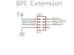
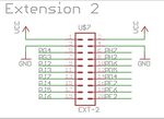
The following pics are for reference. Take note of the location of the U$2 and U$7 symbols on the RAMBo SPI and EXT pics, they are oriented on the board just as they are shown in the pictures. The two ribbon cables supplied with the smart LCD have one red wire on one side of the cable. That is wire 10, so anywhere you see a wire label called out, you can start at the red wire (#10) and count back, or the opposite side (#1) and that will help you in wiring the cables.
The smart LCD board has two connectors on the back. One is labeled EXP1 on the other is EXP2. EXP1 will also be called A in these instructions
- RAMBo EXT and SPI header pin-mapping


Step 2
Note:
This step has been tested and known to work with Arduino 0022 and 0023. If you try another version, and it works, post it here please.
Step 3
Modify your firmware files as shown in the PDF in both fastIO and pins.h, as well as editing your configuration.h file