Rambo
Release status: Working

| Description | An all in one RAMPS class motherboard targeting convenience, reliability, and performance
|
| License | |
| Author | |
| Contributors | |
| Based-on | |
| Categories | |
| CAD Models | |
| External Link |
Contents
Summary
RAMBo (RepRap Arduino-compatible Mother Board) is an all in one RAMPS class motherboard targeting convenience, reliability, and performance.
More info coming soon...
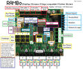
All connectors
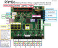
Main connectors
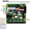
Auxiliary connectors
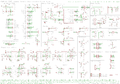
Schematic
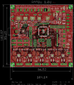
Top/1st copper layer
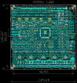
Ground/2nd copper layer
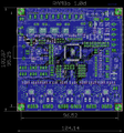
Supply/3rd copper layer
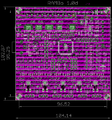
Bottom/4th copper layer


Features
Logic
- Arduino MEGA compatible Atmega2560 and Atmega32u2 processors are compatible with all RAMPS class firmwares
- Crystals for both usb and mcu (timing accurate to 10ppm)
- 4 Thermistor jacks
- All extra pins broken out on both processors (allows using the 32u2 for LUFA AVR programmer, etc.)
- 2 channel SDRAMPS compatible SPI breakout
Motor Drivers
- 5 A4984 1/8th microstep motor drivers (2 connectors on Z for Prusa Mendel)
- Digital Trimpot for stepper current control
- Current limit on driver IC VCC to prevent permanent latchup
- Microstep mode configured by MCU through firmware (no jumpers needed)
- Test points for driver control signals
- Step and Direction pins are on their own ports for synchronous movement capability
- Extra driver ports broke out for up to 3 additional drivers (some of the motor extension pins are shared with max endstop and a pin allocated for SPI-SS extensions)
PWM DC outputs (Extruders, Fans, Etc.)
- 5 outputs
- Low resistance mosfets for cool running
- Indicator led for each channel
Power
- Three independent power rails all accepting 10V-26V input voltage
- Heated Bed 14A
- Extruders 5A (fuse can be exchanged for up to 10A capacity)
- Motors and logic 5A (fuse can be exchanged for up to 10A capacity)
- Built in SMPS for 5V generation from 10V-26V Vin
PCB
- 4 layer
- 2oz copper on all layers
- High quality, High temperature FR4-TG130 PCB
- Gold ENIG finishing
Firmware
Here https://github.com/tonokip/Marlin is Tonokip's Marlin Fork with RAMBo support. It allows setting of the motor current with M907, and microstep mode with M350. Storing to EEPROM is not yet implemented.
USB Driver for new boards
If you are having problems installing the Arduino MEGA 2560 Rev 3 USB driver, it is likely that you you have a newer RAMBo board. If windows is giving you the error that it is an invalid driver, download this file File:RAMBo USBdriver.zip and unzip it into a known location on your computer. In windows 7, plug in your RAMBo board, and let windows fail to find the driver. Then, go to the start menu, right click on computer and click properties. On the left, click on Device Manager. Scroll down to Unknown Devices, and right click on RAMBo. Choose Update driver. CLick on "Browse my computer for driver software", then click on "Let me pick from a list of device drivers on my computer", then click the button for "Have Disk" and then click browse and point it to the file you downloaded above. Then click OK and it will tell you the driver isn't signed, it's ok, install anyways, and enjoy!
Motor Current
The current for the stepper motors is set by firmware controlling the digipot. You can verify the max current for each driver by plugging the reference voltage (VREF) measured at the X_REF test point (Y_REF,etc for the other drivers) in the following formula:
ITripMAX = VREF/0.8
This formula is from the Allegro datasheet : ITripMAX = VREF/(8 X RS). RS = 0.1, the value of the sense resistors.
Schematic

Pins
| Pin Number | Pin Name | Arduino Pin Name | RAMBO Function |
| 1 | PG5 ( OC0B ) | Digital pin 4 (PWM) | PWM-Ext 6 |
| 2 | PE0 ( RXD0/PCINT8 ) | Digital pin 0 (PWM) (RX0) | USB – serial comms, SER0 3 |
| 3 | PE1 ( TXD0 ) | Digital pin 1 (PWM) (TX0) | USB – serial comms, SER0 4 |
| 4 | PE2 ( XCK0/AIN0 ) | Ext2 20 | |
| 5 | PE3 ( OC3A/AIN1 ) | Digital pin 5 (PWM) | PWM-Ext 5 |
| 6 | PE4 ( OC3B/INT4 ) | Digital pin 2 (PWM) | PWM-Ext 4 |
| 7 | PE5 ( OC3C/INT5 ) | Digital pin 3 (PWM) | Bed Heater |
| 8 | PE6 ( T3/INT6 ) | Ext2 18 | |
| 9 | PE7 ( CLKO/ICP3/INT7 ) | Ext2 16 | |
| 10 | VCC | VCC | VCC |
| 11 | GND | GND | GND |
| 12 | PH0 ( RXD2 ) | Digital pin 17 (PWM) (RX2) | Serial 7 |
| 13 | PH1 ( TXD2 ) | Digital pin 16 (PWM) (TX2) | Serial 8 |
| 14 | PH2 ( XCK2 ) | Ext2 8 | |
| 15 | PH3 ( OC4A ) | Digital pin 6 (PWM) | Fan 1 |
| 16 | PH4 ( OC4B ) | Digital pin 7 (PWM) | Heat 1 |
| 17 | PH5 ( OC4C ) | Digital pin 8 (PWM) | Fan 0 |
| 18 | PH6 ( OC2B ) | Digital pin 9 (PWM) | Heat 0 |
| 19 | PB0 ( SS/PCINT0 ) | Digital pin 53 (PWM)(SPI-SS) | SPI-Ext SS 6 |
| 20 | PB1 ( SCK/PCINT1 ) | Digital pin 52 (PWM)(SCK) | SPI-Ext SCK 5 |
| 21 | PB2 ( MOSI/PCINT2 ) | Digital pin 51 (PWM)(MOSI) | SPI-Ext MOSI 4 |
| 22 | PB3 ( MISO/PCINT3 ) | Digital pin 50(MISO) | SPI-Ext MISO 3 |
| 23 | PB4 ( OC2A/PCINT4 ) | Digital pin 10 (PWM) | Z Min Endstop |
| 24 | PB5 ( OC1A/PCINT5 ) | Digital pin 11 (PWM) | Y Min Endstop |
| 25 | PB6 ( OC1B/PCINT6 ) | Digital pin 12 (PWM) | X Min Endstop |
| 26 | PB7 ( OC0A/OC1C/PCINT7 ) | Digital pin 13 (PWM) | LED, PWM-Ext 3 |
| 27 | PH7 ( T4 ) | Ext2 6 | |
| 28 | PG3 ( TOSC2 ) | Ext3 7 | |
| 29 | PG4 ( TOSC1 ) | Ext3 5 | |
| 30 | RESET | RESET | Reset |
| 31 | VCC | VCC | VCC |
| 32 | GND | GND | GND |
| 33 | XTAL2 | XTAL2 | XTAL2 |
| 34 | XTAL1 | XTAL1 | XTAL1 |
| 35 | PL0 ( ICP4 ) | Digital pin 49 | Y Direction |
| 36 | PL1 ( ICP5 ) | Digital pin 48 | X Direction |
| 37 | PL2 ( T5 ) | Digital pin 47 | Z Direction |
| 38 | PL3 ( OC5A ) | Digital pin 46 (PWM) | MX3-5 Direction |
| 39 | PL4 ( OC5B ) | Digital pin 45 (PWM) | MX2-5 Direction |
| 40 | PL5 ( OC5C ) | Digital pin 44 (PWM) | MX1-5 Direction |
| 41 | PL6 | Digital pin 43 | E0 Direction |
| 42 | PL7 | Digital pin 42 | E1 Direction |
| 43 | PD0 ( SCL/INT0 ) | Digital pin 21 (SCL) | I2C SCL |
| 44 | PD1 ( SDA/INT1 ) | Digital pin 20 (SDA) | I2C SDA |
| 45 | PD2 ( RXDI/INT2 ) | Digital pin 19 (RX1) | Serial 5 |
| 46 | PD3 ( TXD1/INT3 ) | Digital pin 18 (TX1) | Serial 6 |
| 47 | PD4 ( ICP1 ) | Ext2 14 | |
| 48 | PD5 ( XCK1 ) | Ext2 12 | |
| 49 | PD6 ( T1 ) | Ext2 10 | |
| 50 | PD7 ( T0 ) | Digital pin 38 | Digipot SS |
| 51 | PG0 ( WR ) | Digital pin 41 | X Microstep2 |
| 52 | PG1 ( RD ) | Digital pin 40 | X Microstep1 |
| 53 | PC0 ( A8 ) | Digital pin 37 | X Step |
| 54 | PC1 ( A9 ) | Digital pin 36 | Y Step |
| 55 | PC2 ( A10 ) | Digital pin 35 | Z Step |
| 56 | PC3 ( A11 ) | Digital pin 34 | E0 Step |
| 57 | PC4 ( A12 ) | Digital pin 33 | E1 Step |
| 58 | PC5 ( A13 ) | Digital pin 32 | MX1-4 Step |
| 59 | PC6 ( A14 ) | Digital pin 31 | MX2-4 Step |
| 60 | PC7 ( A15 ) | Digital pin 30 | Z Max, MX3-4 Step |
| 61 | VCC | VCC | VCC |
| 62 | GND | GND | GND |
| 63 | PJ0 ( RXD3/PCINT9 ) | Digital pin 15 (RX3) | Serial 9 |
| 64 | PJ1 ( TXD3/PCINT10 ) | Digital pin 14 (TX3) | Serial 10 |
| 65 | PJ2 ( XCK3/PCINT11 ) | Ext2 9 | |
| 66 | PJ3 ( PCINT12 ) | Ext2 11 | |
| 67 | PJ4 ( PCINT13 ) | Ext2 15 | |
| 68 | PJ5 ( PCINT14 ) | Ext2 17 | |
| 69 | PJ6 ( PCINT 15 ) | Ext2 19 | |
| 70 | PG2 ( ALE ) | Digital pin 39 | Y Microstep2 |
| 71 | PA7 ( AD7 ) | Digital pin 29 | X Enable |
| 72 | PA6 ( AD6 ) | Digital pin 28 | Y Enable |
| 73 | PA5 ( AD5 ) | Digital pin 27 | Z Enable |
| 74 | PA4 ( AD4 ) | Digital pin 26 | E0 Enable |
| 75 | PA3 ( AD3 ) | Digital pin 25 | E1 Enable |
| 76 | PA2 ( AD2 ) | Digital pin 24 | X Max, MX3-3 Enable |
| 77 | PA1 ( AD1 ) | Digital pin 23 | Y Max, MX2-3 Enable |
| 78 | PA0 ( AD0 ) | Digital pin 22 | MX1-3 Enable |
| 79 | PJ7 | Ext2 13 | |
| 80 | VCC | VCC | VCC |
| 81 | GND | GND | GND |
| 82 | PK7 ( ADC15/PCINT23 ) | Analog pin 15 | Y Microstep1 |
| 83 | PK6 ( ADC14/PCINT22 ) | Analog pin 14 | Z Microstep1 |
| 84 | PK5 ( ADC13/PCINT21 ) | Analog pin 13 | Z Microstep2 |
| 85 | PK4 ( ADC12/PCINT20 ) | Analog pin 12 | E0 Microstep2 |
| 86 | PK3 ( ADC11/PCINT19 ) | Analog pin 11 | E0 Microstep1 |
| 87 | PK2 ( ADC10/PCINT18 ) | Analog pin 10 | E1 Microstep2 |
| 88 | PK1 ( ADC9/PCINT17 ) | Analog pin 9 | E1 Microstep1 |
| 89 | PK0 ( ADC8/PCINT16 ) | Analog pin 8 | Analog-Ext 1 |
| 90 | PF7 ( ADC7/PCINT15 ) | Analog pin 7 | Thermistor 3, Analog-Ext 2 |
| 91 | PF6 ( ADC6/PCINT14 ) | Analog pin 6 | Analog-Ext 3 |
| 92 | PF5 ( ADC5/TMS ) | Analog pin 5 | Analog-Ext 4 |
| 93 | PF4 ( ADC4/TMK ) | Analog pin 4 | Analog-Ext 5 |
| 94 | PF3 ( ADC3 ) | Analog pin 3 | Analog-Ext 6 |
| 95 | PF2 ( ADC2 ) | Analog pin 2 | Thermistor 2 |
| 96 | PF1 ( ADC1 ) | Analog pin 1 | Thermistor 1 |
| 97 | PF0 ( ADC0 ) | Analog pin 0 | Thermistor 0 |
| 98 | AREF | Analog Reference | |
| 99 | GND | GND | GND |
| 100 | AVCC | VCC | VCC |
Source
Development is taking place on Github Latest stable release is in tags - Github tags