Prusa i3 Rework Y axis assembly/pt
|
English • العربية • български • català • čeština • Deutsch • Ελληνικά • español • فارسی • français • hrvatski • magyar • italiano • română • 日本語 • 한국어 • lietuvių • Nederlands • norsk • polski • português • русский • Türkçe • українська • 中文(中国大陆) • 中文(台灣) • עברית • azərbaycanca • |
Introduction | Bill of materials | Y-axis assembly | X-axis assembly | Connecting X-axis and Z-axis | Motor assembly
X and Y-axis motions | Heated bed assembly | Extruder assembly | Electronics and wiring | Marlin Firmware
Contents
Montar a mesa aquecida

Partes necessárias :
- Parte em alumínio como base da mesa
- Y Belt Holder - peça de plástico impressa
- 3x Rolamento linear ref.: LM8UU
- 2x parafusos de M3x14 mm
- 2x Anilha de Ø3 mm
- 2x porca para parafuso M3
Montar a peça impressa "Y Belt Holder" no suporte em alumínio com dois parafusos M3x14 mm (pode necessitar de cortar o excesso dos parafusos visto que o alumínio é de 6mm de espessura e do Y Belt Holder é de 4 mm de espessura os parafusos passam 4 mm (o lado da cama aquecida)), duas anilhas Ø3 mm e duas porcas M3. A orientação da peça impressa "Y Belt Holder" não é muito importante.
Coloque 3 rolamentos lineares LM8UU fixando-os com abraçadeiras, fazendo-as passar pelos pequenos orifícios na placa de alumínio, corte o excesso das abraçadeiras.
Peças necessárias:
- 4x peças impressas "Y Corner"
- 1x peça impressa "Y Idler"
- 1x peça impressa "Y Motor"
- 1x rolamento de esferas 608
- 4x Varões roscados M10x210 mm
- 22x porca M10
- 22x anilha Ø10 mm
- 1x Parafuso M8x30 mm
- 1x porca M8
- 2x Ø8 mm wahser
- 1x Parafuso M4x20 mm
- 1x Porca M4
Passo 1
Fure usando uma broca de 10 mm os buracos dos quatro "Y Corner" (apresentados a verde). O ideal será colocar o berboquim no sentido de rotação inverso para furar gradualmente sem danificar as peças impressas.

Passo 2
Montagem do "Y Idler": insira no seu interior uma porca M4 e aparafuse um parafuso M4x20 mm. Caso tenha alguma dificuldade, pode aquecer ligeiramente a porca com um soldador ao mesmo tempo de a empurra (cuidado para não queimar a peça, nem aquecer demasiado a porca). Insira um rolamento de esferas 608 na ranhura e faça passar um parafuso de M8x30 mm com uma anilha de Ø8 mm e uma porca de M8. Pode ter de forçar a entrada do parafuso, mas para evitar danificar a peça, é preferível que enrosque até passe a peça para o outro lado. No fim aperte ligeiramente de forma a ficar firme.

Passo 3
Insira o "Y Idler" assembly in the middle of a threaded rod M10x210 mm and between two Ø10 mm washers and two M10 nuts. Do not tighten the nuts. Thread a M10 nut and washer about 30 mm on both ends. Do the same with a threaded rod M10x210 mm.

Step 4
Slide two threaded rods M10x210 mm on the Y Motor and fix it with four M10 nuts and four Ø10 washers. Do not tighten the nuts. Thread a M10 nut and washer about 30 mm on both ends.

Step 5
Take two Y Corners, the Y Idler assembly and the threaded rod M10x210 mm and fix them with four Ø10 washers and four M10 nuts. Do the same with the Y Motor assembly with two Y Corners. In both cases, adjust the distance between two Y corners (186 mm). Slightly tighten the nuts.
Assembly with the longitudinal parts
Needed parts :
- Heated bed mount assembly
- Transverse parts
- 2x Smooth rod Ø8x350 mm
- 2x Threaded rod M10x380 mm
- 12x M10 nut
- 12x Ø10 mm washer
Step 1
Take two threaded rods M10x380 mm, slide two Ø10 mm washers and thread two M10 nuts in the middle. Thread a M10 nut and washer about 30 mm on both ends.

Step 2
Insert the previous rods in a transverse side and fix them with two Ø10 mm washers and two M10 nuts. Do not tighten the nuts yet.
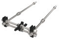
Overview of step 2
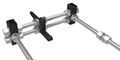


Step 3
Insert two smooth rods Ø8x350 mm in Y Corner top until the end. Slide the Heated bed mount assembly on both smooth rods carefully.

Step 4
Insert the last transverse side on smooth rods Ø8 and threaded rods M10. Fix them with two M10 nuts and two Ø10 mm washers. Fasten the smooth rods with four zip-ties.
Tighten with a wrench the entire assembly with care. Make sure that the four Y Corners touch the ground. Do not tighten Y Motor and Y Idler nuts.

To finish, make sure that the Y-axis move smoothly. Otherwise, verify the distance between Y Corner lateral faces (186 mm).
Resolução de dúvidas e Suporte
Caso não entenda alguma instrução pode contactar-me através do link RepRap.pt.