Prusa i3 Rework Electronics and wiring/ua
|
English • العربية • български • català • čeština • Deutsch • Ελληνικά • español • فارسی • français • hrvatski • magyar • italiano • română • 日本語 • 한국어 • lietuvių • Nederlands • norsk • polski • português • русский • Türkçe • українська • 中文(中国大陆) • 中文(台灣) • עברית • azərbaycanca • |
Introduction | Bill of materials | Y-axis assembly | X-axis assembly | Connecting X-axis and Z-axis | Motor assembly
X and Y-axis motions | Heated bed assembly | Extruder assembly | Electronics and wiring | Marlin Firmware
Contents
Встановлення електроніки
Потрібні частини
- RAMPS
- Arduino Mega 2650
- 4x stepsticks
- 3x Arduino washer
- 3x M3x24 mm screw
- 3x M3 nut
- 3x Ø3 mm washer
Крок 1
Встановіть плату RAMPS на Arduino Mega 2560. Можливо, Вам знадобиться зрізати з'єднаня, що знаходяться під роз'ємом живлення RAMPS. Обидва роз'єми повинні бути підключені.
Крок 2
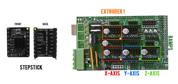
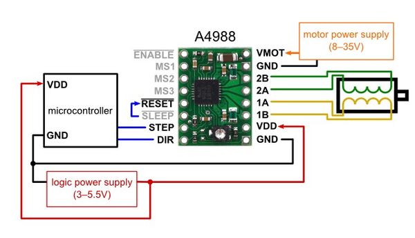
Підключіть кожний контролер крокового двигуна відповідно до схеми нижче. Зверніть увагу на три джампери під кожним контролером. Одне місце залишаеться вільним для підключення, наприклад, другого екструдера. Також зверніть увагу, що контури крокових двигунів пронумеровано 1 та 2, де 1A та 1B відносяться до першого контуру, а 2A and 2B до другого.
Крок 3
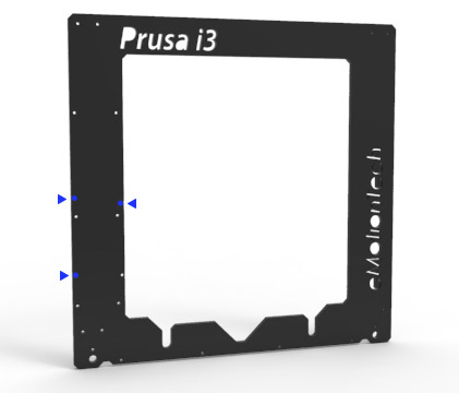
Закріпіть зібрану електроніку ззаду алюмінієвої рами за допомогою трьох Arduino шайб для забезпечення ізольованого з'єднання. Зорієнтуйте роз'єми живлення ВГОРУ (в оригінальній інструкції написано ВНИЗ, але орієнтація отворів Prusa I3 не дозволить такого розміщення). Використайте три M3x24 мм гвинти, три Ø3 мм шайби (для RAMPS) та три гайки M3.
З'єднання дротів
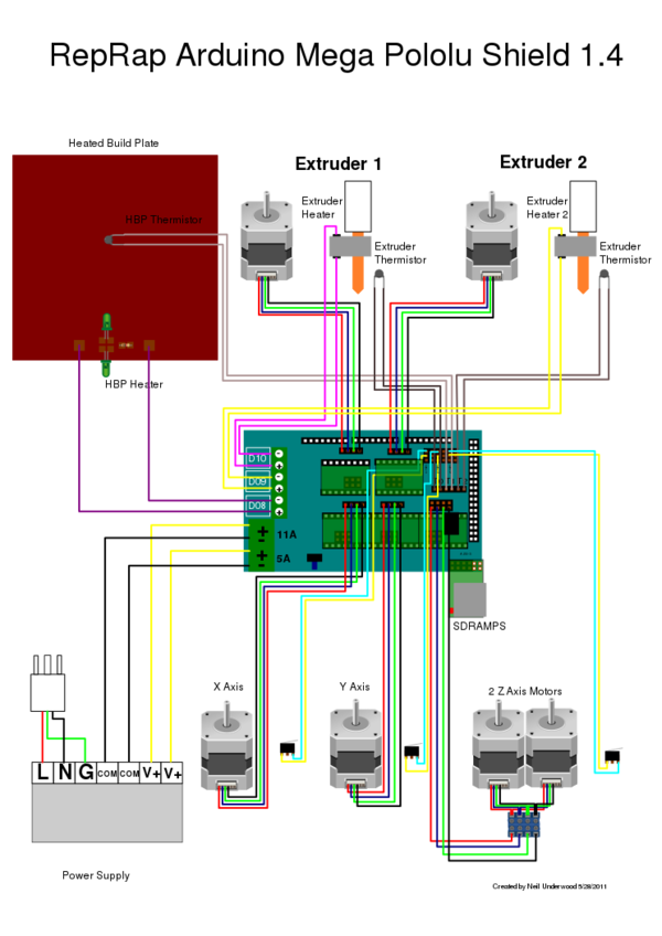
Всі з'єднання винесені на наступній схемі : LIEN PAGE REPRAP
Зауваження : Замість другого екструдера можна під'єднати вентилятор для охолодження надрукованої моделі.
З'єднання кінцевих вимикачів (Endstop)
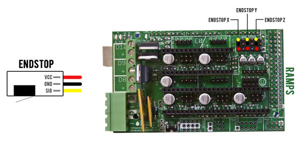
Підключіть три вимикачі (Endstop) до RAMPS за допомогою трижильних дротів (дроти з позначкою « Endstop ») відповідно наступної схеми. На схемі зображено підключення для X, Y, and Z min вимикачів. Якщо у Вас є, наприклад, Y max вимикач, його потрібно підключити праворуч до Y min. :
Motors wiring
You have to connect both Z-axis NEMA 17 motors to work in parallel. To do that, weld both power supply wires (cut in a previous step) according to their colors : red/red, green/green, blue/blue and black/black. We strongly recommend you to protect each weld with heat shrink tubing or an insulating adhesive tape. Note: the RAMPS 1.4 allows you to plug in two Z-axis motors, so cutting/welding of the wires might not be needed.
NEMA 17 wires color can change depending on the supplier and there is no risk in case of a wrong wiring. Indeed, the wires are always associated in pairs (one pair for each coil). SO there is no risk if the color of supply wires doesn’t match the wiring diagram.
Hot End resistor and PCB heatbed wiring
The Hot End (or extruder) resistor is not polarized and is plugged to D10.
PCB heatbed is plugged to D08. Make sure to not invert the positive and negative poles.
Thermistors wiring
The thermistor is not polarized. So you can connect the PCB heatbed thermistor and the Extruder thermistor in both ways.
Fans wiring
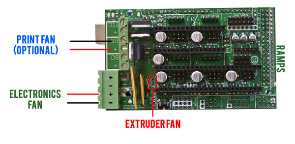
Plug the extruder fan directly to its dedicated power supply pins (see illustration below).
If you have a fan which cools the electronics then plug it directly to the RAMPS.
If you have a fan which cools the print then plug it to D9.
Power supply wiring
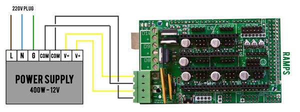
The principle power supply wire is not included. You have to strip an end of a power cable and to connect to the power supply (L, N, G plugs). Make sure to do this operation properly.
The power supply is connected to the RAMPS with additional connecting wires. You have to strip both ends, make sure to follow the scheme correctly.
Check the power supply for 110volt vs 220volt operation.
