PonokoExtruderAssembly
Assembling the Ponoko RepRap Extruder
UNDER CONSTRUCTION
Construction and assembly of the Extruder is quite demanding. There is a 3mm hole to be bored straight down a 40mm long rod, a 0.5mm hole to be drilled and some rudimentary lathing to be done. If you have a smattering of DIY skills, you should be able to accomplish this with a power drill and a few nifty tricks. If not feeling quite up to the challenge and unable to find a helpful person with a lathe nearby, buy the bits from the RRRF, Diamond Age, or BitsFromBytes.
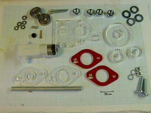
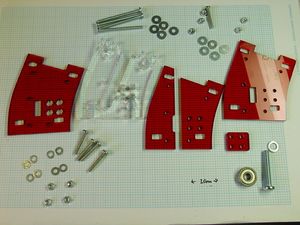
Start by finding the components and fastenings as shown. We'll build the Extruder Heater Assembly later.
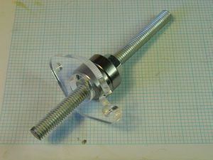
Take a piece of M8 studding 110mm long and wind a nut down it about 60mm. Add two 680Z "sk8er b0y" bearings and a 12mm o/d M8 spacer cut from 4.5 or 5mm acrylic. Add the Extruder Bearing Stop, making sure the notch in it faces anti-clockwise when viewed from the top of the M8 studding as shown
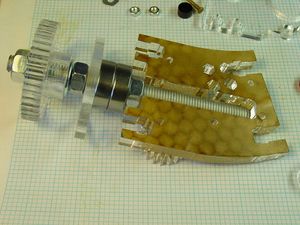
Screw on another nut, add a washer and the 20mm o/d M8 spacer cut from 8mm acrylic. Screw on another nut, slip on the large gear wheel and secure with a washer and nut. Shuffle the nuts so that when the lower nut is held against the neck of the 8mm Extruder Body Segment, the bottom of the studding misses the end of its slot by about 1mm as shown:
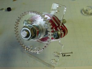
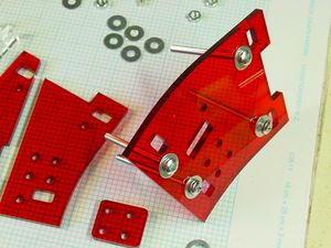
Put washers on the two M5 30mm screws and put them into the Bearing Stop - it'll be very hard to do this soon without removing the large gear. From the other (let's call it bottom) end of the M8 studding, slide on the Extruder Motor Bracket, taking care to align the small notch with the one on the Bearing Stop. Then slide on two 3mm Extruder Bearing Brackets and one 5mm Extruder Bearing Bracket so that the two 608Z bearings are completely enclosed. Put nuts on the two M5 30mm screws loosely, just to hold things together while we fit the Extruder Motor.
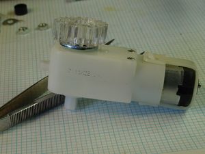
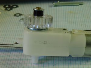
Two kinds of motor are supported, and they both have different shaft sizes. Pick the smaller 8mm acrylic gear with the appropriate centre hole for your motor's shaft. If none fit your motor, make with a Dremmel tool or epoxy as appropriate. Put two M8 washers on first, then fit the gear.
Find a small woodscrew or truncate a slightly oversized one. The thread only goes half way up a woodscrew so you'll need an M3 spacer or stack of washers to take up the slack. DO NOT just drive the screw into the motor's gearbox!
The M8 washers should hold the gear above the annoying little projections on the gearbox case.
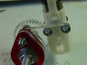
Slip washers onto two M3 30mm screws and use them to hold the motor onto the Motor Bracket. If you need to modify the bracket to take your motor, ensure that the gears mesh closely. The motor bracket will flex in use.
By adding washers underneath the motor on one side or the other, it is possible to make the motor lean towards or away from the large gear and thus bodge around any minor imperfections in bracket modification...
Secure with washers and nuts.
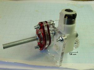
The Extruder Motor Assembly is now complete and can be put safely to one side.
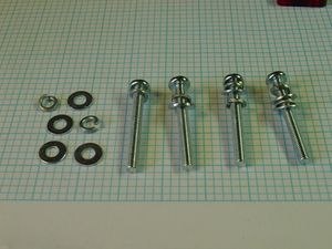
Now to assemble the Extruder Body. This holds the screw thread and incoming filament together, driving it towards the heater barrel. Here is what a set of parts looks like, short eight absconding M3 spring washers:
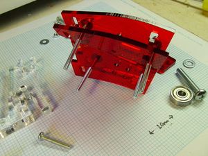
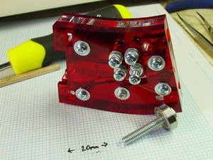
Start by putting large M3 washers on the M3 40mm screws, and put them into the front of the Extruder Body segments. That's the one with the square group of 4 holes in it, not a square group of hexagonal holes. Your parts may have less cat hair than mine, but that's okay:
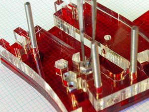
Fit the two parts of the divided segment on next. There should be a 3mm channel dividing the two parts. That's where the filament goes.
Add the 8mm segment. Now is a good time to pop 4 M3 nuts in each of the hexagonal holes. It can be done later, but now is easier if the holes are tight.
Slide on the final segment, add washers and nuts - do not tighten, this is just to hold things in place while we do the wiring.
Secure with M3 20mm screw through the central hole with a nut and washers. This can be tightened.
Make the Extruder Idler by slipping a 625ZZNSK bearing onto an M5 30mm screw with a relatively small head. That was hard, eh?
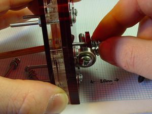
If you have four small, stout springs, put them on four M3 20mm screws. Otherwise, put a split washer on each screw, then a small M3 washer, then a spring washer, then another plain one as shown.
Use the four split washer assembles one by one to attach the small rectangular Extruder Idler Clamp, clamping the Idler in place over the window in the front of the Extruder Body.
Just catch the four M3 20mm screws in the semi-captive nuts in the Extruder Body, trapping the Extruder Idler in place, do not tighten fully or you'll not get the filament in.
It may be helpful to push on the semi-captive nuts when inserting the screws. A chopstick seems to do the job.
Get a piece of 3mm filament about 250mm long and poke it into the slot that goes down the middle of the laminated Extruder Body.
Remove the M5 nuts from the Extruder Motor Assembly and put the filament through the feed hole. If the feed hole is rough or too tight, ream it with a 3mm or 1/8" drill.
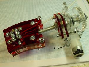
Put the two M5 nuts into the slots in the Extruder Body and fasten the Motor Assembly and Body together, ensuring that the filament can still move smoothly. I actually found it easier to reach the M5 screws by temporarily removing the large gear.
Now you can tighten the screws with the split washers a bit to grip the filament. When you can't easily move it, it's gripped. Do not over-tighten or you'll break the clamp.
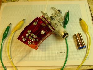
Wire up a few volts across the motor and check everything moves - including the filament. Slacken and tighten nuts, wriggling segments if necessary.
Preen.
Tighten the M8 nuts.
Build a PTFE Extruder Heater Spacer. Basically this is a 43mm piece of 10mm diameter PTFE rod with a 3mm hole drilled down the centre. One end of the hole is chamfered, the other end tapped for 6mm with an M6 hole. Use a 4.5mm starter hole for the tap as PTFE is very soft.
No lathe? Me neither. I use an electric drill as a lathe. Basically you rotate the workpiece and file it to shape things like the nozzle or chamfering. If you've not been taught to use one, go look up the safety precautions and please at least wear safety goggles. Be warned that lathes are very efficient at sucking loose things in, like hair and clothing, or alternatively throwing things out very fast, like chuck keys.
To drill centred holes, construct some kind of movable vice-like holder for the drill bit (nice and sharp please). An old chuck? Some metal plate and a lot of clamps? Old drill press? I use a Z-Vise2, a pipe clamp and some G-clamps.
When you advance the bit into the workpiece, as long as you're basically on centre physics keeps you there. Do pause occasionally to let the swarf (curly waste bits) out. Take your time and do not even come close to stalling the drill. This is more difficult with harder materials.
Build a heater barrel. This is a 40mm long piece of M6 brass bolt with a 3mm hole drilled right down the middle. Make it say 45mm long and file off the worst end. Chamfer the hole on the end that will screw into the PTFE and make the other end as flat as you can to give a good seal on the nozzle. Clean the threads.
Plaster an element to the heater barrel. Use 8 ohms of nichrome wire - a 200-300mm length depending on the wire. The insulated "Pelican Wire" sold by the RRRF is ideal.
Use smooth fireproof cement according to the maker's instructions. Avoid overly coarse furnace cement as it drops bits.
Lay down one layer, dry and shape, wrap with wire. Put the windings slightly closer together - but not even close to touching - at the nozzle end.
Cover with more cement. Dry as per manufacturer's instructions and then fire in an oven to curing temperature - or put it in with the roast and trust to luck like I did.
Some cements - a small-scale test is a good idea - fuse when heated to red heat in a blowtorch and go very solid. If done when not quite dry, this also causes the outermost layer to go puffy and insulating yet solid as a rock.
Do not heat the filament ends more than cherry-red. You can burn through the filament if you try hard like I did. It sucks, as the youths will have it.
If you're using a thermistor or thermocouple heat sensor that does not come with a tag, make one out of a piece of copper sheet. I use flattened out copper water pipe. Epoxy the sensor to it with high-temperature metal-loaded epoxy such as JB Weld or the better class of stuff for fixing heatsinks.
Solder the wiring up to a D15 as per the Darwin extruder instructions. Fit the D15 to the Extruder D15 Mounting Bracket before connecting up both ends of all the wires.
Remove nuts & washers from the M3 40mm screws. Add four M3 8mm acrylic spacers, the Mounting Bracket, washers and nuts. You might not want to tighten up until you know it fits the Extruder Socket on the X Carriage.
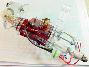
The final extruder all ready to plug in.
Wonderful.
If you want to use more than one material or want a ready spare, make another one.
-- Main.VikOlliver - 31 Oct 2008
