PiBot for Repetier SD LCD Controller
Revision as of 03:37, 20 October 2013 by Panxinlong7373 (talk | contribs)
|
English • العربية • български • català • čeština • Deutsch • Ελληνικά • español • فارسی • français • hrvatski • magyar • italiano • română • 日本語 • 한국어 • lietuvių • Nederlands • norsk • polski • português • русский • Türkçe • українська • 中文(中国大陆) • 中文(台灣) • עברית • azərbaycanca • |
Release status: working

| Description | Part of PiBot Electronics Expand Board
|
| License | |
| Author | |
| Contributors | |
| Based-on | [[]]
|
| Categories | |
| CAD Models | see files
|
| External Link |
- PiBot for Repetier SD LCD Controller is a part of PiBot electronics. It put forward a easy solution to enrich the functions of your 3D printer and CNC machine. This project not only an electronic product, but also PiBot-Manual-shank included, which is similar to the handheld box that made of cold-drawn steel.The technology of grit and black oxide finish dose used in PiBot-Manual-shank fabrication.
Contents
Description
The PiBot for Repetier SD LCD Controller is a Expand Board of the PiBot Electronics.
- Features of Expand Board
- Expand functions: keys, TF card, LCD-2004 or Lcd-1602.
- Use the Push-Push Type TF card socket, which is more reliable and convenient. You can easily get one TF card from the Smart phone.
- 74HC4050D based level shifter. it is high-speed Si-gate CMOS device, and it's more reliable compare to the resistance divider.
- IDC-20pin terminal used. It means these anti-plug linker is very convenience,fast and reliable.
- build-in pins assignment silk in the Top Over layer. Easy apply them to other program.
- LCD-2004 is assorted. LCD-1602 is compatible. 2 Control bus & 4 data bus.
- 12*12mm Omron buttons, more convenient and pleasing to the eye. Color: White(Black background) Shape: Round
- Communication mode : All pins is parallel communication.
- PCB Board Size: 63.8*54.2 mm Fix hole:56.9*38.2 mm Color: Black
- For purchasing or more information, please contact PiBot, or one of the resellers.
- Any idea to develop this Extension Board, you can ask [Pan Xinlong].
- All parts are licensed under CC BY-NC-SA 3.0 .
Design Goals
- Designer for Repetier and PiBot-Manual-shank .
- Offers a reliable and high price performance ratio handheld manual controller.
- Easy use for DIY enthusiast, convenience for secondary development.
Purchase URL
- PiBot for Repetier Motherboard $39.00: http://www.pibot.com/index.php/pibot-for-repetier-motherboard.html#.UmNs17LBjVk
- PiBot TB6600 Stepper Driver $19.99: http://www.pibot.com/index.php/pibot-stepper-driver-board.html#.UmNtibLBjVk
- PiBot for Repetier SD LCD Controller $29.99: http://www.pibot.com/index.php/pibot-for-repetier-sd-lcd-controller.html#.UmNtU7LBjVk
- PiBot Endstop $2.29: http://www.pibot.com/index.php/pibot-endstop.html#.UmNnCLLBjVk
Parts List & Ports
- Parts List of PiBot for Repetier SD LCD Controller
| Qnty | PartNr | Device | Footprint |
| 1 | D1 | Led Red | led-0805-a |
| 1 | C1 | 10uF | 0805c |
| 1 | C2 | 104 | 0603c |
| 1 | U1 | 74HC4050 | SOP16 |
| 4 | K1,K2,K3,K4 | Switch 12*12mm | Key |
| 1 | Dis1 | LCD-1602/2004 | sip16/curved needle |
| 1 | K5 | reset button | SMD Tact switches |
| 1 | P1 | ExpandPort-2.54mm | DC3-20-254 |
| 1 | K5 | reset button | SMD Tact switches |
| 2 | R1,R2 | 2K,10K | 0603r |
| 1 | R3 | VR3.79-10K | Potentiometer |
| 1 | TFcard socket | Push-Push Tyep TF card socket | TFcard socket |
| 4 | P4,P5,P6,P7 | fix hole | Point |
- Ports of PiBot for Repetier SD LCD Controller
- The IDC-20Pin terminal is anti-plug linker, we can easy use.
- The LCD port's first pin is the rectangular pad. Other pin number is progressive increase.
How to Build
- Solder Images

- Prepare all of the components to build a PiBot for Repetier SD LCD Controller;
- You'll need a soldering toolkit and SMT soldering toolkit to finish this board.

- Use SMT soldering toolkit
- Apply solder paste to every exposed SMD pad.
- Place each SMD component on its appropriate pad.
- Place populated board on a cold hotplate,turn hotplate on,board solders itself!
- Solder in remaining through hole components.
- If you without a soldering toolkit, you can also use an tweezers and an soldering iron finish them by manual. All of them are hand solderable!

- Use soldering toolkit
- Insert through hole components.
- solder all these pins to the pad.

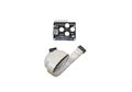
IDC-20 terminal
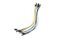
flexible flat cable
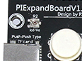
Adjust the Vo about 0.8V to the GND


- Hardware Test & Debug
- Before plug in the IDC-20 cable, you need to check the chip and diode.
- Connect the LCD port and the LCD input pin with flexible flat cable.
- Use an digital multimeter to test the resistance value of the power. Usually, it has a increase resister. Ensure no short cut and insufficient solder.
- For the first time, We should Change the LCD's Vo(LCD bias signal,pin 3) to a right value, so you can see the content in the LCD. Usually,Keep 0.8V to the GND voltage(The power source is 5V).
- If all measure OK, you can plug in the IDC-20 cable now, and the power LED (red) lighten.
- If you have been finish mother board uploaded((Repetier firmware)), and it work, we'll see the display content upload to the LCD. LCD work.
- The content display in the LCD change and the buzzer sounds when you push down these four button. Key ok.
- Plug in and out the TF card, test the TF card detect function. Press "OK" button, and click the "next" button find the TF card item, press "OK" key. If the TF card is plugged in and have the **.gco or .gcode file we will find it and run.
the PiBot for Repetier SD LCD Controller is default use Repetier Host and
Firmware
- You can find the pin assignment in Repetier firmware.
- Download the Repetier firmware and Code editer Arduino IDE or Source Insight
- Unzip the Repetier firmware, open your Arduino IDE
- Select the Board type "arduino mega 2560" in "Tools\Board\arduino mega 2560" and the "Serial Port" in "Tools\Serial Port\COM**"
- Open file Repetier.pde or "Repetier.ino" in "Repetier Unzip file\Repetier-Firmware\src\ArduinoAVR\Repetier\Repetier.pde" or "Repetier Unzip file\Repetier-Firmware\src\ArduinoAVR\Repetier\Repetier.ino".
- Select configuration.h set #define MOTHERBOARD 315 (PiBot for Repetier V1.4) or #define MOTHERBOARD '314 (PiBot for Repetier V1.0-1.3)
- set #define DRIVE_SYSTEM 0 (full cartesian system, xyz have seperate motors.) & #define FEATURE_CONTROLLER 8( PiBot Display/Controller extension with 20x4 character display) or #define FEATURE_CONTROLLER 9 (PiBot Display/Controller extension with 16x2 character display).
- Click the "Verify" button to compile the code or direct click "Upload" button to compile and upload firmware to PiBot for Repetier mother board.
- Other firmware maybe compatible too, but you need to configure it. Such as:Marlin firmware.
Troubleshooting
- If you can't upload the firmware, Please check the Aduino tools setting and press the "reset button" once the compile finished.
- If the LCD can't display, please check the connection and check the Vo value.
Future development
- Both the 4-Pin I2C port and 20-Pin IDC3 port integrated, it much be a more powerful one.