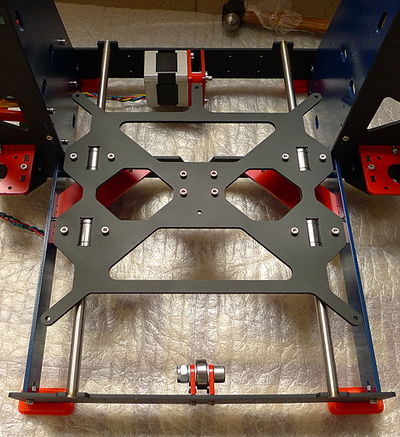
P3Steel Y axis assembly
We'll do this in four easy steps:
- Y idler end assembly.
- Y motor end assembly.
- Y smooth rods and carriage installation.
- Y belt installation.
Each step requires 15~20 minutes, so set aside one evening for the Y axis assembly.
Contents
Y idler end assembly
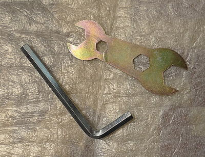
For this step we require these tools (besides the M3 hex key we used to assemble the frame):
Y motor end assembly
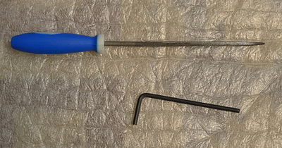
For this step we require these tools:
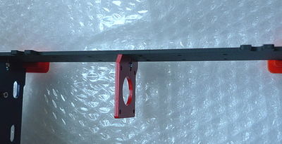
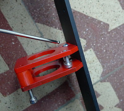
We begin by installing the left Y motor end support, this requires 1 x 12mm M3 bolt and 1 x M3 nyloc nut. Note the orientation of the part.
We can now (try to) install the stepper motor. You'll notice at this point that the M3 nyloc nut interferes with the stepper. That is the single (relatively easy to fix) issue I have found with Irobri's awesome CAD design of the P3Steel frame!
OK, to fix this we need the small metal file, since we are going to file a small notch in the stepper body:
Y smooth rods and carriage installation
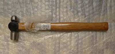
We need a small hammer (not kidding!) to gently (again, not kidding!) push the Y-axis smooth rods into their corresponding slots in the steel frame.
