OptoEndstop 2.1
Contents
Opto Endstop v2.1
Overview
<div class="thumb tright"></div>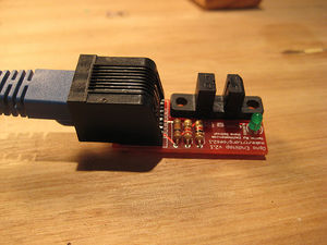
Darwin's Cartesian axes all need a datum (also known as home position or end-stop) to reference their movements. At the start of each build each axis needs to back up until the datum point is reached. For Darwin, we use one opto-switch for each axis to define its position. The opto switches also help protect the machine from moving past its intended range and damaging itself.
You will need 3* (three) of these for a basic RepRap machine, and *6 (six) of them for a full machine with both home and end stops.
For those using the ZD1901 opto interrupter prevalent in the Southern Hemisphere, a simple stripboard assembly is required. Details here.
- You'll need a soldering toolkit to do most of this.
- Read our Electronics Fabrication Guide if you're new.
Get It!
Full Kit
Raw Components
Files
<div class="thumb tright"></div>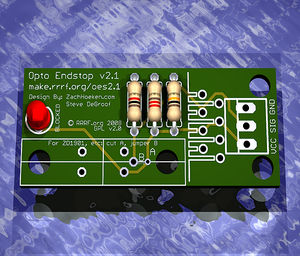
You can download the electronics files from Sourceforge.
This file contains the following:
- GERBER files for getting it manufactured
- PDF files of the schematic, copper layers, and silkscreen
- Eagle source files for modification
- 3D rendered image as well as POVRay scene file
- exerciser code to test your board.
Schematic
<div class="thumb tright"></div>
Interface
Debug LED
Output
Build It
Board Bugs (listed by version)
- No bugs yet, please report any you find to the forums.
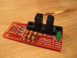
Printed Circuit Board
<div class="thumb tright"></div>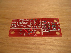
You can either buy this PCB from the RepRap Research Foundation, or you can make your own. The image above shows the professionally manufactured PCB ready for soldering. Its also cheap, only $0.75 USD.
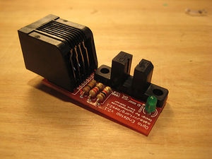
Components
<div class="thumb tright"></div>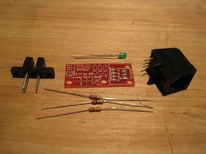
<iframe src="http://parts.reprap.org/embed/module/Opto+Endstop+v2.1" width="550" height="400" frameborder="0">Visit http://parts.reprap.org/embed/module/Opto+Endstop+v2.1</iframe>
Soldering Instructions
<div class="thumb tright"></div>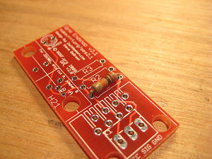
R1 - 10K ohm (Brown - Black - Orange)
Insert the resistor in any orientation. Double check the color bands.
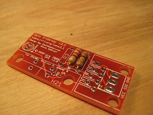
R2 - 220 ohm (Red - Red - Brown)
Insert the resistor in any orientation. Double check the color bands.

R3 - 1K ohm (Brown - Black - Red)
Insert the resistor in any orientation. Double check the color bands.
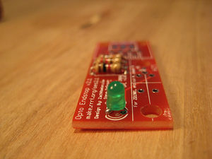
Blocked/Debug LED
The LED must be inserted in the proper orientation. Insert the short leg (negative) into the hole closest to the flat size of the silkscreen.
H21LOB
This is the opto switch. It can only be inserted in one direction. Insert it and solder it info place.
RJ45 Jack
THIS BOARD DOES NOT SUPPORT ETHERNET! We are simply using the jack to provide simple, easy, cheap connectors.
Insert the jack (it should snap into place) and solder it into place.
TODO: add alternative wiring with .100" headers.
Test It
<div class="thumb tright"></div>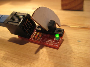
TODO: add testing information here.
Use it!
TODO: usage information here.