OptoEndstop 2.1
Contents
Opto Endstop v2.1
Overview
<div class="thumb tright"></div>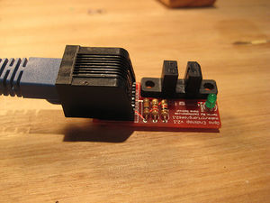
Darwin's Cartesian axes all need a datum (also known as home position or end-stop) to reference their movements. At the start of each build each axis needs to back up until the datum point is reached. For Darwin, we use one opto-switch for each axis to define its position. The opto switches also help protect the machine from moving past its intended range and damaging itself.
You will need 3* (three) of these for a basic RepRap machine, and *6 (six) of them for a full machine with both home and end stops.
For those using the ZD1901 opto interrupter prevalent in the Southern Hemisphere, a simple stripboard assembly is required. Details here.
- You'll need a soldering toolkit to do most of this.
- Read our Electronics Fabrication Guide if you're new.
Get It!
Full Kit
Raw Components
Files
<div class="thumb tright"></div>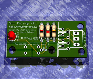
You can download the electronics files from Sourceforge.
This file contains the following:
- GERBER files for getting it manufactured
- PDF files of the schematic, copper layers, and silkscreen
- Eagle source files for modification
- 3D rendered image as well as POVRay scene file
- exerciser code to test your board.
Schematic
<div class="thumb tright"></div>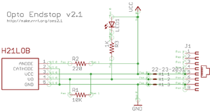
Interface
<div class="thumb tright"></div>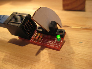
Debug LED
The debug LED is a visual indicator of the actual state of the switch. Please note: due to the constraints of the circuit, the LED status is inverted from the actual signal. What this means is that when the output is high, the LED is off and when the output is low, the LED is on. See the table below for more information:
Output
The output of the switch is a binary value that represents the state of the switch. LOW = 0v/GND and HIGH = 5V. The output of the circuit depends on the particular model of opto switch used. RepRap has recently switched from the H21LOI to the H21LOB due to the wider availability of the H21LOB.
The H21LOI and H21LOB are identical, except their outputs are inverted respective to each other. This requires a change in firmware to interpret the input appropriately. Below are truth tables that describe the different outputs the circuits provide.
H21LOB Truth Table
| Status | Output | LED |
| Open | HIGH | Off |
| Closed | LOW | On |
H21LOI Truth Table
| Status | Output | LED |
| Open | LOW | On |
| Closed | HIGH | Off
|
Physical Connection
The v2.x series of Opto Endstop is an experiment in standardization of connectors. One of the major problems with the previous v1.0 design is that it required the end user to construct their own connectors which was a tedious and error prone process. The new v2.x design has 2 different connector footprints: the old .100" spaced connector as well as an RJ45 connector. It is up to the end user to decide which connector they would like to use.
RJ45 Connector
Say it with me:
The opto endstop v2.x design does not support ethernet!
The opto endstop v2.x design does not support ethernet!
The opto endstop v2.x design does not support ethernet!
What we are doing is hijacking a common and very cheap connector for our own purposes. RJ45 patch cables and jacks are ubiquitous, versatile, robust, and cheap. We've considered and rejected many other connector technologies (RJ11, 3.5mm audio cables, etc) but in the end, RJ45 is the best for our needs. If you have another source of high quality premade cables (that we have not already rejected) please bring it to our attention in the forums. Please do not complain about being forced to use these cables, as there is a simple on-board alternative (see below).
Below you will find a pin out table containing the pin-out information on a standard RJ45 patch cable.
| Pin | Color | Function |
| 4 and 5 | 5V supply | |
| 6 | Signal | |
| 7 and 8 | Ground |
.100" Spaced Header
In order to maintain backwards compatibility, as well as giving the user the freedom to chose their desired connector technology, we have included a standard, .100" pitch connector footprint that you may populate as desired. The pins are clearly labeled, and you may wire it however you like. You can solder wires directly to the board, solder in right-angle headers, normal headers, or any other number of technologies. Its up to you as a user to decide. Instructions on usage of alternative connectors are described below.
Build It
Board Bugs (listed by version)
- No bugs yet, please report any you find to the forums.
Printed Circuit Board
<div class="thumb tright"></div>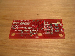
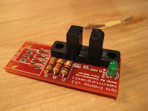
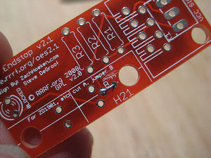
You can either buy this PCB from the RepRap Research Foundation, or you can make your own. The image above shows the professionally manufactured PCB ready for soldering. Its also cheap, only $0.75 USD.
Components
<div class="thumb tright"></div>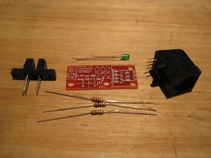
<iframe src="http://parts.reprap.org/embed/module/Opto+Endstop+v2.1" width="550" height="400" frameborder="0">Visit http://parts.reprap.org/embed/module/Opto+Endstop+v2.1</iframe>
Soldering Instructions
<div class="thumb tright"></div>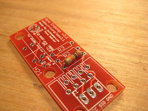
R1 - 10K ohm (Brown - Black - Orange)
Insert the resistor in any orientation. Double check the color bands.
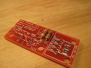
R2 - 220 ohm (Red - Red - Brown)
Insert the resistor in any orientation. Double check the color bands.

R3 - 1K ohm (Brown - Black - Red)
Insert the resistor in any orientation. Double check the color bands.
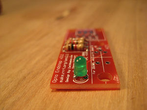
Blocked/Debug LED
The LED must be inserted in the proper orientation. Insert the short leg (negative) into the hole closest to the flat size of the silkscreen.
H21LOB
This is the opto switch. It can only be inserted in one direction. Insert it and solder it info place.
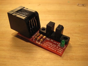
RJ45 Jack
THIS BOARD DOES NOT SUPPORT ETHERNET! We are simply using the jack to provide simple, easy, cheap connectors.
Insert the jack (it should snap into place) and solder it into place.
Using Alternative Connectors
TODO: add alternative wiring with .100" headers.
ZD1901 Opto Switch
The board also supports using simpler opto isolators that may be more prevalent in your area (say New Zealand). One such opto switch is the ZD1901 opto switch. This is a 4-pin opto switch and it is relatively easy to hook up. There are actually instructions on the board which we'll illustrate below:
<div class="thumb tright"></div>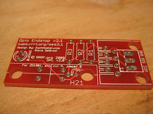
Step 1: Cut trace marked 'A'
Cut this trace with an exacto knife, dremel, or other suitable sharp instrument. Take care not to hurt yourself or any of the other traces.
Step 2: Jumper holes marked 'B'
In order to get the signal properly routed, take a small piece of wire and solder it in place as shown to connect the two holes together.
Step 3: Solder ZD1901 in place
Solder the ZD1901 in place making sure to insert it in the proper orientation.
Test It
<div class="thumb tright"></div>TODO: add testing information here.
Use it!
TODO: usage information here.