Metamaquina 3D/Instruções de montagem/Extrusor
Contents
Components
Instruções
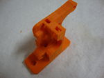
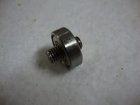
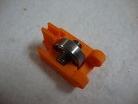
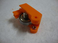
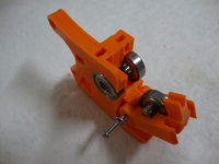
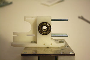
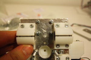
Passe o pequeno pedaço de barra roscada por um rolamento e encaixe-os na parte interna da pinça. Encaixe também uma porca M3 no espaço onde passará o parafuso que se comportará como dobradiça.
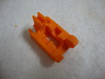
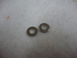
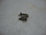
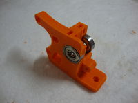
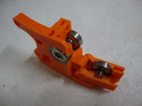
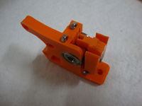
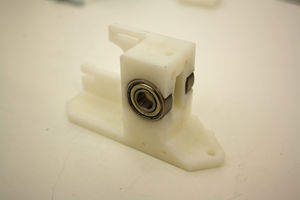
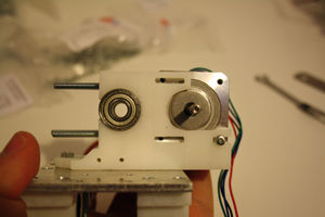
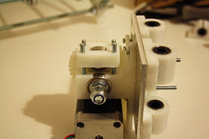
Encaixe dois rolamentos 608zz em seus respectivos lugares no bloco extrusor. Prenda a pinça com um parafuso M3x25 sem se esquecer da arruela M3.
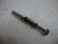
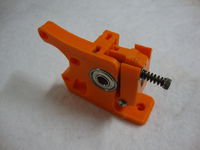
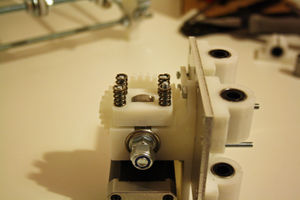
Introduza porcas M4 nas cavidades preparadas na parte superior do bloco extrusor. Em um parafuso M4x50, coloque uma mola CM2083 e uma arruela M4, nesta ordem. Atarrache os parafusos nas porcas citadas anteriormente e uma trava de pressão para pinça está pronta.
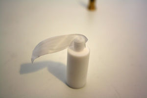
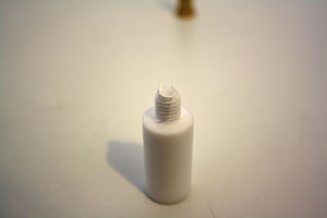
Take the PTFE insulator and wrap a few turns of the PTFE tape around the threaded section.
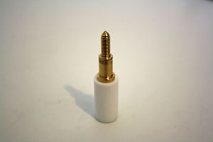
Take the brass nozzle and screw on to the PTFE insulator.
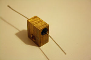
Using the Silicone sealant fix the heating resistor in to the smooth board hole in the brass heater block.
Wiring the Hot End
Montagem do corpo do extrusor
Components
Instructions
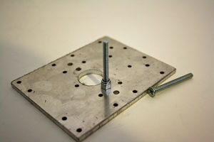
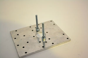
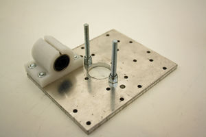
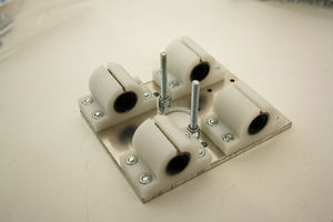
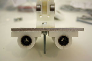
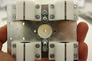
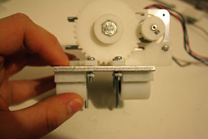
Take the two M4 counter sunk 40mm screws and attach to the X axis plate through the countersunk holes , fix in place with a M4 nyloc nut on the underside.
Attach the LM8UU holders using the M3 12mm countersunk screws and M3 nuts.
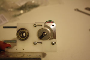
Push two 608zz bearings in the holes on the Extruder block. (NOTE this can be a tight fit, gently squeezing in a vice can help ensure the 608zz bearings are seated correctly)
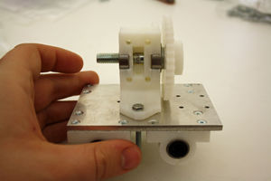
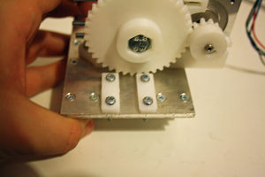
Use the two M4 16mm bolts to attach the extruder block to the X axis plate and use two M4 nyloc nuts to secure it in place.
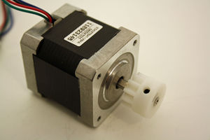
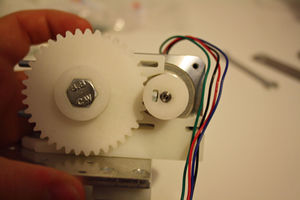
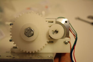
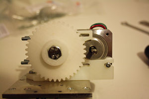
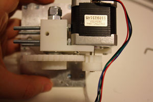
Attach the Drive gear to the extruder stepper motor ensuring the grub screw lines up with the flat section of the stepper motor shaft. Fit as shown in photo below.
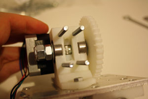
Attach the four M4 50mm bolts through the bolt shaped holes on the extruder block. Hot End assembly
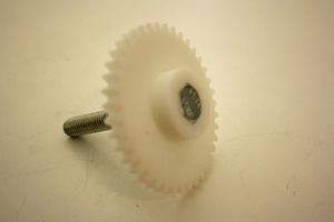
Take the hobbed bolt and attach the Hub gear to it. Add two M8 washers.
Attach the hobbed bolt assembly to the extruder block, attaching to the side of the extruder block with the motor mount.
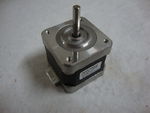
Take the extruder stepper motor and hold in place so that the gears engage with each other. You will note that two of the stepper mounting holes are covered by the Hub gear, use one M3 8mm screw to hold the stepper motor in place. Remove the drive gear from the motor shaft, and then remove the hobbed bolt assembly. Attach the stepper motor in place with the remaining two M3 8mm screws which holes are now no longer covered.
Re attach the hobbed bolt assembly, fix in place with one M8 washer, one M8 nut and one M8 nyloc nut.
Re attach the drive gear to the stepper motor shaft, ensuring the grub screw lines up with the flat section of the motor shaft.
Attach the two belt clamps using four M3 16mm screws and four M3 nuts, do not fully tighten yet.
Insert a 608zz bearing with the 20mm threaded rod and attach the Extruder idler holder to the extruder block to hold it in place.
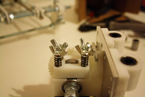
Add a spring to each of the bolts followed by a M4 wing nut. Do not over tighten.
