LaserCut Mendel Post processing
Introduction
Throughout the intructions on this page we have taken photos and provided a description about how to perform the "Post Processing" of the LaserCut parts, when you are done with these steps, you will have a set of LaserCut parts which are ready for assembly into the LaserCut Mendel.
It is assumed that your skills and abilities with the tools and materials involved are adequate for the job, advanced skills should not be required, but your ability to pay attention to detail and handle the pieces accurately will make a big difference on how your machine fits together later. We are not in any way trying to teach you the skills needed to process these parts. Along with that, we do not get into any safety discussions, and OFTEN in the photos provided, there is no safety equipment shown, this is intentional to make the image of the steps more clear. You should always always use and follow safety instructions which came with your equipment.
I feel bound to warn you that the tools involved can be dangerous! They can remove fingers, and put holes into your body. If this makes you nervous, please re-read the introduction, before deciding to tackle these steps yourself.
Post Processing has three main processes to it, Routing, Drilling and Gluing/Clamping. Some of the major components (listed in the Table Of Contents below) require only one of these and others require more, I note which processes are involved.
Contents
- 1 Introduction
- 2 Tools used
- 3 Frame Vertices
- 4 Z Bar Top Clamp
- 5 X Axis Carriage
- 6 X Axis Vertical Drive Plate 180 end
- 7 X Axis Vertical Drive Plate 360 end
- 8 Y Axis Bearing 180
- 9 Y Axis Bearing 360
- 10 Y Axis Bar Clamp (Style 1)
- 11 Y Axis Bar Clamp (Style 2)
- 12 Y Axis Idler
- 13 Y Axis Motor Mount
- 14 Z Axis Belt Tensioner
- 15 Z Axis Motor Bracket
- 16 Z Axis Leadscrew Base
Tools used
To perform the following procedures, you will need these tools:
- Router Table
- 5/16 in Diameter or 8mm Roundover Routing bit - This is not a common size bit, don't assume you can buy it at your local hardware store. I had to have mine custom made!
- Drill Press
- 21/64 in Diameter or 8.5mm Drill bit
- 0.154 in diameter or 4mm Drill bit
- An assortment of small clamps (I use spring clamps, other will work too)
- Good wood glue, I use a polyurethane glue, but other should work
I also use a micro-pin nailer, but you can glue and clamp each piece, where I have pinned them (pinning just saves clamps and in many cases time).
Frame Vertices
Processes: Glueing/Clamping, and Drilling
LaserCut Pieces Used:
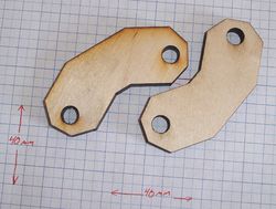
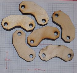
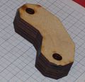
Although the picture only shows 2 LaserCut Pieces, there are twelve of them and they are glued together to create 6 vertices, as shown in the following picture:
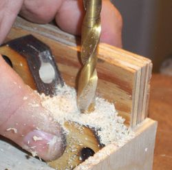
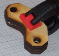
After the glue has dried, the vertices need drilled. I created a jig to help hold my vertices in the correct position and to keep them square and upright. Take extra care to get these holes positioned just right, having them off center will cause serious problems squaring your machine. You may also find that you need to trim excess glue from the parts, in order to get them to sit squarely in the jig.
The holes are centered the one direction. The other direction they are placed as closely to the lasercut holes as it can be without intersecting them.
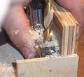
Here are a few more pictures we took while performing the above processes.
Z Bar Top Clamp
Processes: Routing
LaserCut Pieces Used:
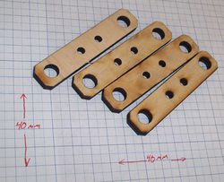
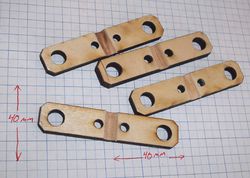
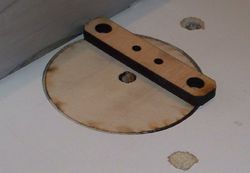
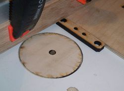
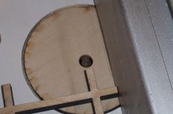
The processing on these is fairly simple, we route a groove in the center of the clamp piece, to hold the Z Axis Smooth bar firmly.The picture on the left is before processing, the picture on the right is after processing.
X Axis Carriage
Processes: Glueing/Clamping
LaserCut Pieces Used:
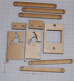
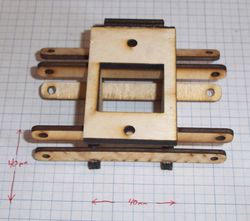
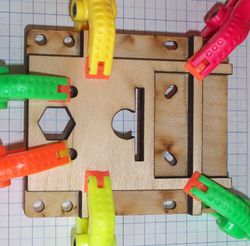
The pieces shown on the Left are used to make the X Carriage as it is shown on the right.
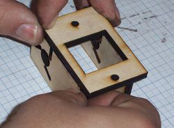
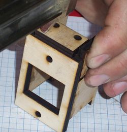
Two of the bearing supports are fatened to the front of the X carriage (see picture of processed X Carriage above) They are centered and glued as far to the top and bottom of the space provided as possible. The other three bearing supports are not fastened into the carriage, so that they can be removed to clamp the X belt into place.
X Axis Vertical Drive Plate 180 end
Processes: Routing, and Gluing/Clamping
LaserCut Pieces Used:
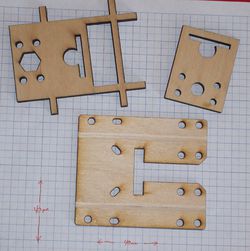
The three pieces shown on the Left are used to make the X Axis Vertical Drive Plate, 180 degree end, as shown on the right.
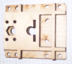
Next take the reinforcing piece and glue it to the piece you just routed, but on the opposite side. You line up the ends of the reinforcement with the edges of the plate, (see picture on Right).
The smaller piece is also glued to the bearing plate - I recomend waiting until the top piece has dried before gluing the bottom piece. It is glued to the bottom (where the shallow grooves were routed). Take extra care to properly line up this pice, with the one you just glued on top. I usually take some of the bearing supports and a small squaring jig that I have made, to make sure that the ends of the slots for the bearing supports line up. It is also possible to help line these up using a bearing support and a small square.
Here are some more pictures taken while processing this part:
X Axis Vertical Drive Plate 360 end
Processes: Routing, and Gluing/Clamping
LaserCut Pieces Used:
Y Axis Bearing 180
Processes: Glueing/Clamping
LaserCut Pieces Used:
Y Axis Bearing 360
Processes: Glueing/Clamping
LaserCut Pieces Used:
Y Axis Bar Clamp (Style 1)
Processes: Routing
LaserCut Pieces Used:
Y Axis Bar Clamp (Style 2)
Processes: Routing
LaserCut Pieces Used:
Y Axis Idler
Processes: Glueing/Clamping
LaserCut Pieces Used:
Y Axis Motor Mount
Processes: Glueing/Clamping
LaserCut Pieces Used:
Z Axis Belt Tensioner
LaserCut Pieces Used:
Z Axis Motor Bracket
LaserCut Pieces Used:
Z Axis Leadscrew Base
LaserCut Pieces Used:
