ITopie Build Manual/fr
|
English • العربية • български • català • čeština • Deutsch • Ελληνικά • español • فارسی • français • hrvatski • magyar • italiano • română • 日本語 • 한국어 • lietuvių • Nederlands • norsk • polski • português • русский • Türkçe • українська • 中文(中国大陆) • 中文(台灣) • עברית • azərbaycanca • |
Contents
Obtenez les sources
La première chose dont vous avez besoin est une copie locale des fichiers sources ( OpenSCAD , DXF , STL , etc ... ) .
La façon la plus simple de l'obtenir est de télécharger / cloner le répertoire git https://github.com/lautr3k/RepRap-iTopie .
Pour cela utiliser la commande
git clone https://github.com/lautr3k/RepRap-iTopie.git
ou
wget https://github.com/lautr3k/RepRap-iTopie/archive/dev.zip
Fabriquer la structure
If you do not want a customized version, you can simply use the generated DXF files in the ./build/output directory for milling/cutting your frame.
Si vous ne voulez pas une version personnalisée , vous pouvez simplement utiliser les fichiers DXF générés dans le ./build/output répertoire pour réaliser le fraisage/découpe de votre cadre .
Version Découpe CNC
./build/output/iTopie_plates-CNC-16mm_thickness.dxf
Version Découpe Laser (expérimentale)
./build/output/iTopie_plates-LaserCut-16mm_thickness.dxf
Fabriquer une structure sur mesure
Configuration
Si vous voulez réaliser une stucture personnalisée, vous avez besoin de OpenSCAD (version 2015.03-1) pour éditer et compiler les fichiers sources scad.
Après avoir installé OpenSCAD, lancer le et selectionnez "Design->Automatic Reload and Compile" et"View->Hide editor".
Maintenant vous pouvez ouvrir le fichier ./scad/main.scad pour une vue en temps réel de toutes les modification faite dans le fichier de configuration.
Ouvrez le fichier de configuration ./scad/config.scad dans votre éditeur favori pour réaliser les changements.
(Chaque fois que le fichier sera enregistré sur le disque ( à partir de l' éditeur externe ) , OpenSCAD va reconnaître les changements dans ce fichier et recompiler automatiquement le projet pour afficher ces changements en temps réel.)
Générateur de fichier DXF
La méthode recommandée est d'utiliser le script python situé dans le répertoire ./build. Cela générera pour vous un fichier DXF unique et propre avec les différentes couches en prenant en compte les modification dans du fichier de configuration ./scad/config.scad.
Utilisation
Utilisation : build.py [-h] [--target int] [--output_type int] [--output_dir path]
                [--output_file filename] [--output_clean] [--tmp_dir path]
                [--tmp_clean] [--odmt path] [--scad path] [--openscad path]
                [--clean] [--version]
Options
Arguments facultatif :
  -h, --help            affiche ce message d'aide et se termine.
  --target int
                        type de découpe (valeur par défaut : 0)
                        ----------------------------
                        0 : Découpe CNC (par défaut)
                        1 : Découpe Laser
  --output_type int, -t int
                        type de sortie (valeur par défaut: 0)
                        -------------------------
                        0 : tout (feuille 1 et feuille 2 en un seul fichier)
                        1 : feuille 1 (horizontal_plate, y_carriage, feet)
                        2 : feuille 2 (vertical_plate, triangles, feet)
  --output_dir path, -d path
                        dossier d'enregistrement du fichier de sortie (valeur par défaut: ./output)
  --output_file filename, -f filename
                        nom du fichier de sortie sans extension (valeur par défaut: auto)
  --output_clean        supprime tous les fichiers du répertoire de sortie (défaut: false)
  --tmp_dir path        chemin du répertoire temporaire (valeur par défaut: ./tmp)
  --tmp_clean           supprime tous les fichiers du répertoire temporaire (valeur par défaut: true)
  --odmt path           chemin de l'outil de fusion OpenSCAD DXF (valeur par défaut: ../odmt/odmt.py)
  --scad path           chemin du fichier principale OpenSCAD (valeur par défaut: ../scad/main.scad)
  --openscad path       chemin de l'exécutable OpenSCAD binary (valeur par défaut: C:/Program Files/OpenSCAD/openscad.exe)
  --clean, -c           supprime tous les fichiers du répertoire de sortie et temporaire (valeur par défaut: false)
  --version, -v         affiche la version du programe et se termine.
Examples
python build.py -f iTopie_plates-CNC-16mm_thickness
Crée iTopie_plates-CNC-16mm_thickness.dxf in the defaut ./build/output répertoire.

Build manual
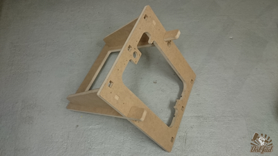
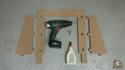
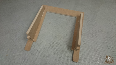
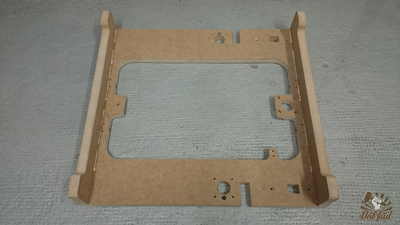
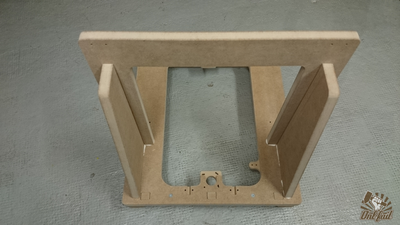
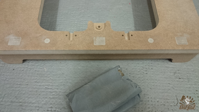
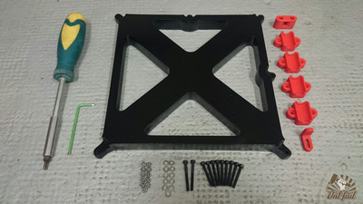
Frame assembly
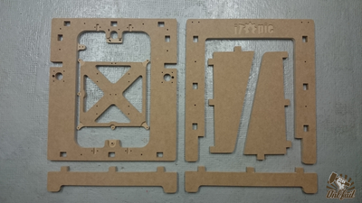
All frame parts you need.
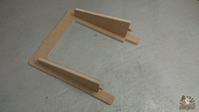
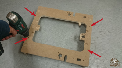
Fit the rears triangles on the "U" part.
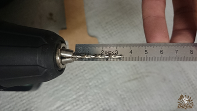
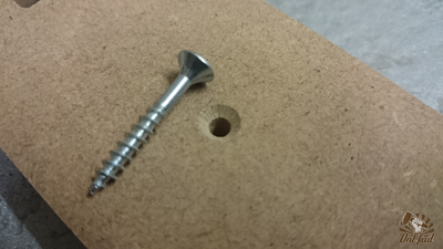
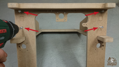
Take a 3mm drillbit and adjuste to 3.5cm from the mandrel.
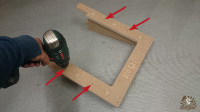
Make some holes. (4x)
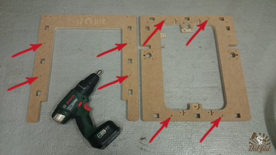
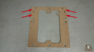
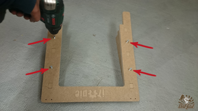
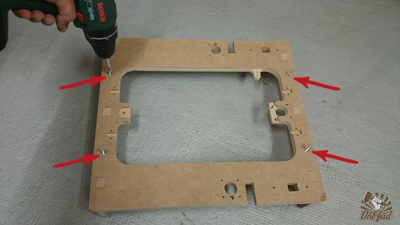
Fit the assembly on the "O" part.
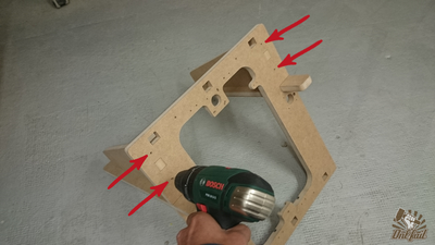
Make more holes. (4x)
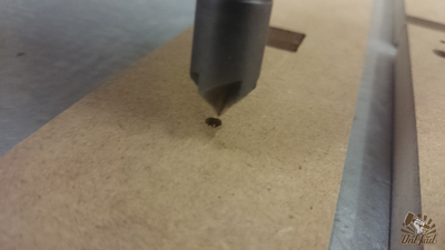
Remove all parts and remake again the holes in depth. (8x)
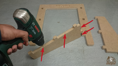
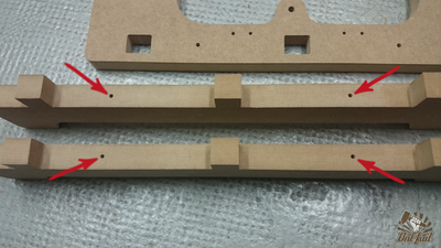
Ok !, Fit the feet on the "O" part.
Turn back and... yes ! more and more holes. (4x)
Same as above, unplug the parts and remake the holes. (4x)
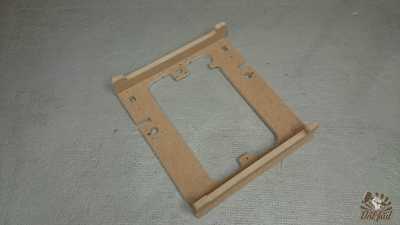
The chamfers, optional but recommended.
"O" part back side chamfers positions.
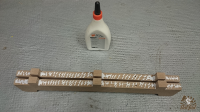
Glue and screws party.
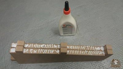
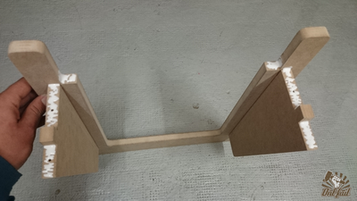
Apply some glue on the two triangle.
Re-Fit the rear triangle on the "U" part and press hard.
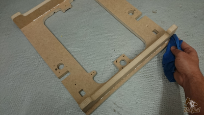
Turn back and screw all together wite four 3.5x40mm screws.
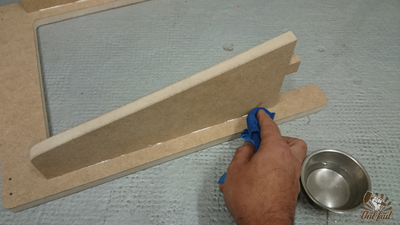
With a wet cloth, wipe the superfluous glue.
Take the feet and apply some glue.
Plug the feet and press hard.
Turn back and screw all together wite four 3.5x40mm screws.
As before, clean the glue.
Apply some glue as pictured.
Fit all together and press hard.
Turn back and screw all together wite four 3.5x40mm screws.
Do not forget to clean the glue.


At this point your frame is finished and functional. The following statement is optional but highly recommended.
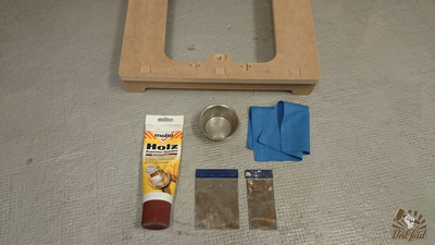
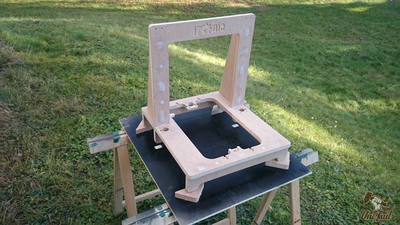
Frame puttying, sanding, painting and lacquering
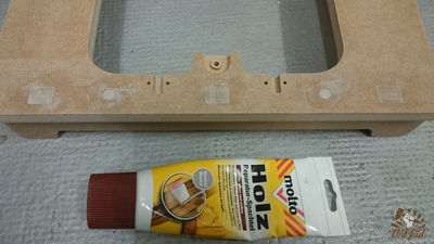
Apply some wood putty, over screws head and frame connectors.
When the putty is dry, sand superfluous.
Clean dust from sanding.
Find a good place for painting.
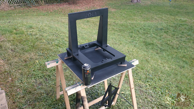
Apply color (two coats).
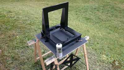
Apply the lacquer (two coats).
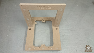
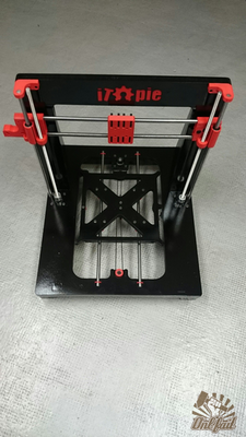
Glue the printed iTopie logo.
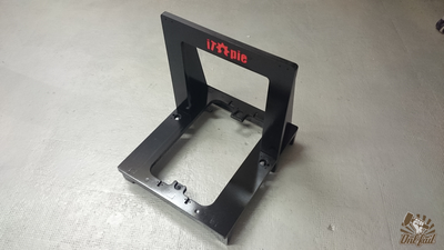
Frame assembly done!


X Axis (1/2)
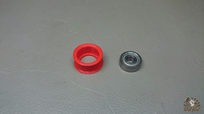
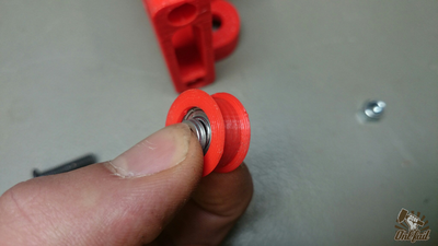
Take one 605(z) bearing and the printed flange.
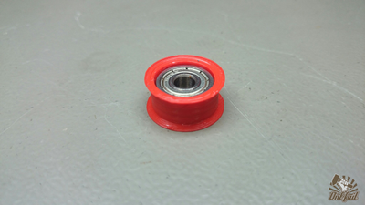
Insert the 605(z) bearing in the printed flange.

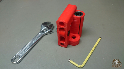
Take the x-end (idler side) and two LM8UU bearing.
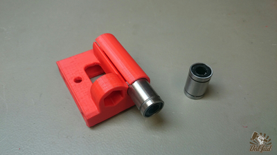
Push the two bearing in the x-end.
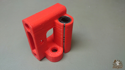
Once is done.
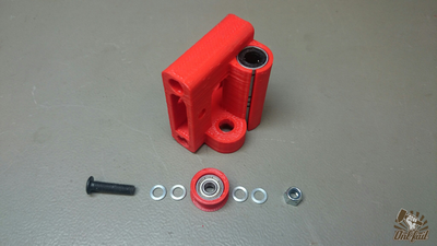
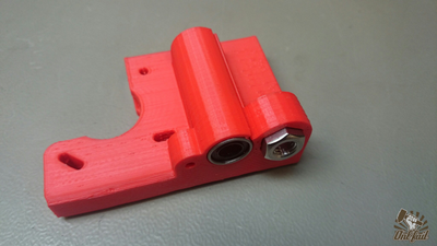
Take one M5x20mm screw, four washers of 1mm thick and one M5 nylock nut.
Put two washers one each side of the idler bearing.
Slid the bearing in the x-end, and lock wite the screw/nut.
Push one M8 nut on each x-end.
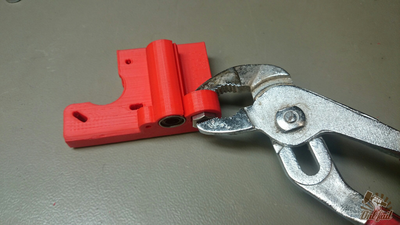
If needed, use a pliers.
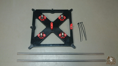
Take four LM8UU, eight zip ties and the x-carriage.
Push the four LM8UU on the x-carriage.
Secure with zip ties.
Take the two x-end, and the two 380mm smooth rods.
Insert the two rods in one x-end.
Slide the x-carriage and clip the other x-end to complete.


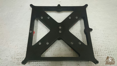
Y Axis
11 x M3 nuts
12 x M3 washers (do not rely on the image)
11 x M3 x 30mm screws (do not rely on the image)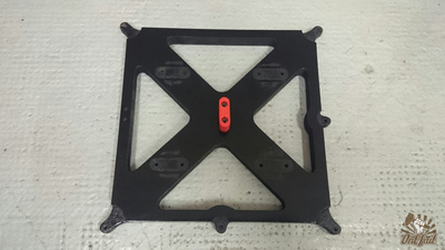
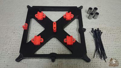
Securely tighten the belt holder with two screws (washers and nuts) in the center of the y-carriage.
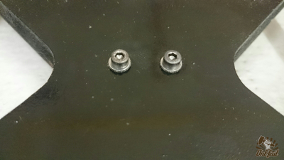
Do not forget to add a washer on each screw.
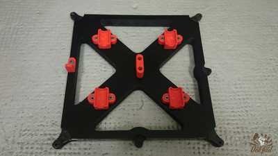
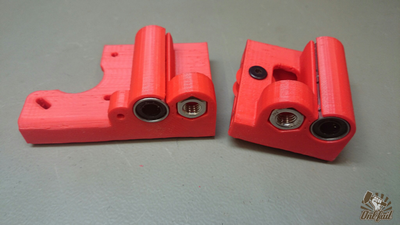
Loosely tighten the four LM8UU holders with two screws (washers and nuts) on each. We must tighten thoroughly later.
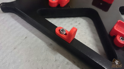
Attach the flag of the limit with a washer on each side.
Pay attention to the orientation of the plate and the flag.
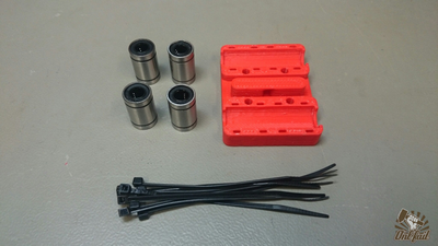
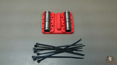
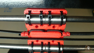
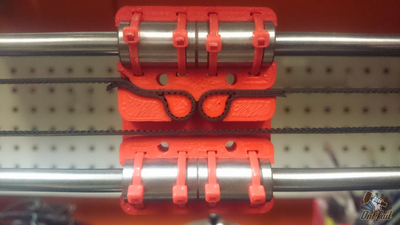
4 x LM8UU
8 x zip ties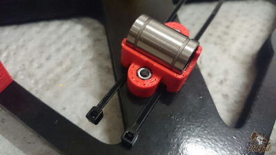
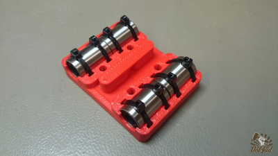
Firmly press the bearing in the holder and tighten the zip ties thoroughly.
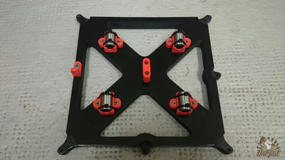
The same with the others.
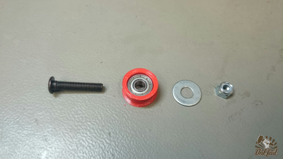
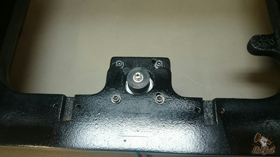
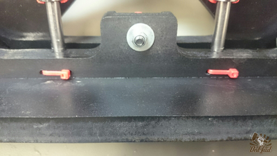
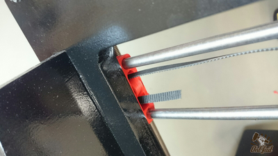
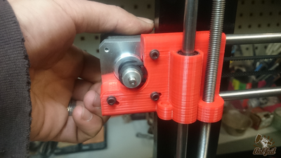
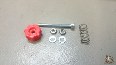
1 x M5 x 25mm
1 x 605(z) bearing
1 x printed flange
1 x M5 washer
1 x M5 nylock nut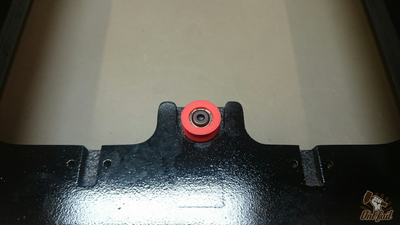
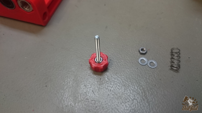
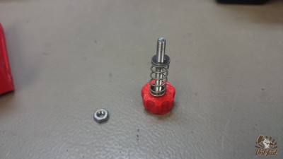
Place the flanged bearing in place and insert the screw.
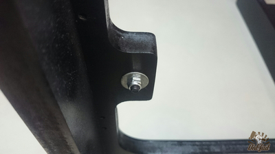
Add on other side the washer and nut and tighten firmly.
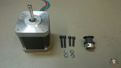
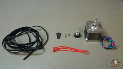
1 x Nema 17 motor
4 x M3 washers
2 x M3 x 22mm screws
2 x M3 x 16mm screws
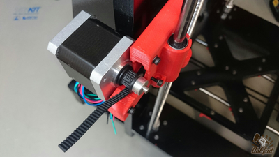
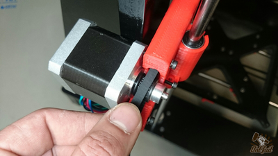
1 x toothed pulley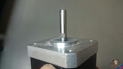
Make a groove on the shaft of the motor for a good tightening of the pulley.
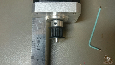
Adjust the pulley, the belt must be positioned between one and two centimeters from the base of motor.
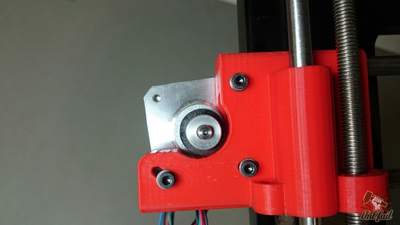
Secure the motor to hold it in place. Do not overtighten.
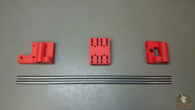
2 x 400mm smooth rods
8 x zip ties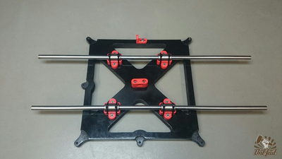
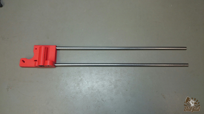
Slide the two smooth rods.
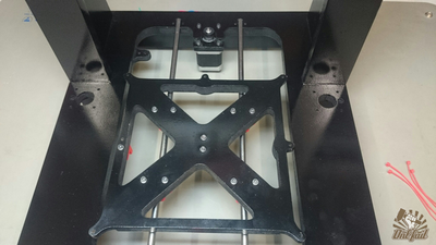
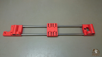
Clip the assembly in the frame.
Secure the bar with the zip ties.
It's time to tighten the four LM8UU holders of the y-carriage. Check that the carriage moves properly between each clamping.
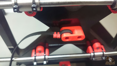
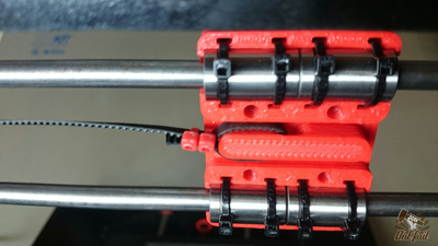
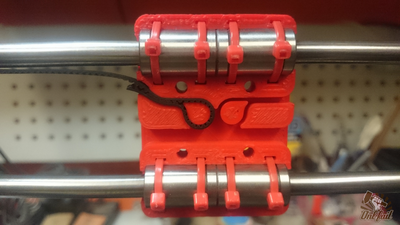
Attach the 800mm GT2 belt with two zip ties on is holder at the center of the carriage.
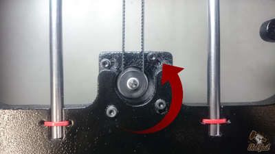
Pass the belt around the motor pulley. Make sure the engine is released (turn left).
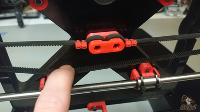
Pass the belt around the idler pulley and tie it back to the center.
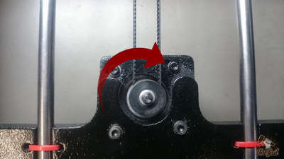
To tighten the belt turn the motor clockwise and tighten.
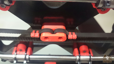
The belt is tight and the Y axis is done.


Z Axis
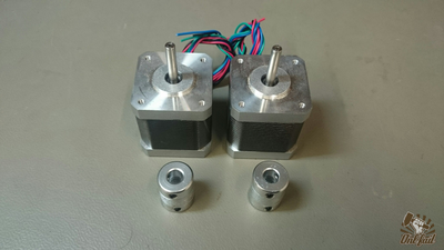
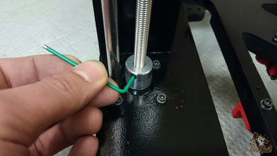
Take two nema 17 motor and two coupler. Fix the two coupler on the shaft of the motor.
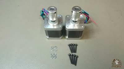
8 x M3 x 20mm screws
8 x M3 washers
Firmly secure the two motor on the frame.
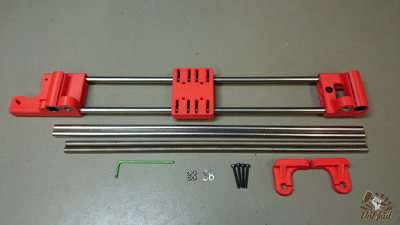
1 x X-axis assembly
2 x 380mm smooth rods
2 x 360mm threaded rods
4 x M3 x 25mm screws
4 x M3 washers
4 x M3 nuts
2 x Z rod holder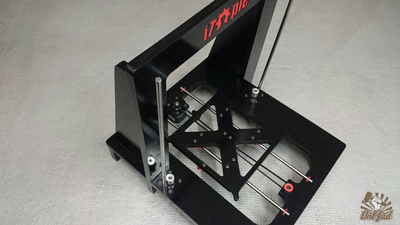
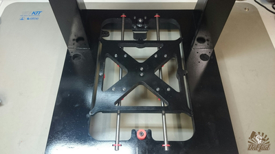
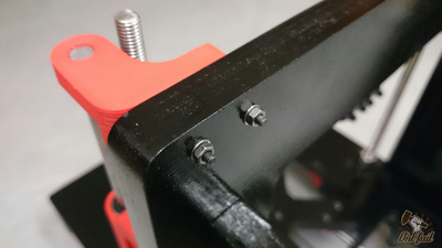
Clip the two smooth rods in the frame.
Make sure it is fully inserted, use a hammer if necessary.
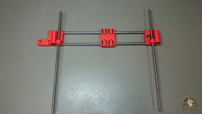
Screw the two threaded rods in the assembly.
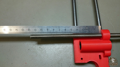
Screw around 10/15 cm from the top.
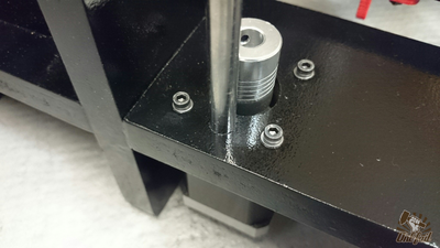
Slide the assembly on the smooth rods and guid the threaded rods into the couplers.
Firmly tighten the couplers.
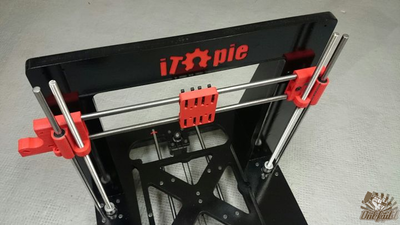
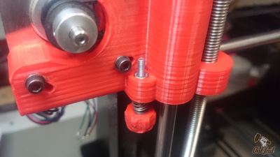
Insert the two top bracket on the smooth rods.
Adjust the brackets and secure them to the frame with two M3 x 20mm screws.
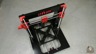
Z axis is done!


X axis (2/2)
1 x 900mm GT2 belt
3 x M3 x 20mm screws
3 x M3 washers
1 x toothed pulley
1 x Nema 17 motor
4 x zip ties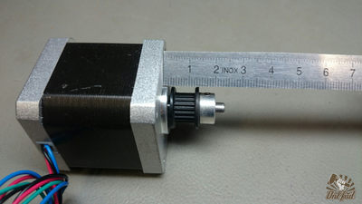
Adjust the pulley, the belt must be positioned between 0.5 and 1.2 centimeters from the base of motor.
Secure the motor on x-end to hold it in place. Do not overtighten.
Attach the 900mm GT2 belt with two zip ties on is holder at the center of the carriage.
The same with the x-carriage v2 alternative.
Pass the belt around the idler pulley.
Pass the belt around the motor pulley.
Tie it back to the center of the carriage.
Attach the 900mm GT2 belt with two zip ties on is holder at the center of the carriage.
The same with the x-carriage v2 alternative.
To tighten the belt turn the motor clockwise and tighten.

X axis is done!


Endstops
X axis
Y axis
Z axis
...
...
...
...


