Hall-O DIY kit
Release status: working
| Description | Hall effect endstop sensor
|
| License | Attribution - ShareAlike
|
| Author | |
| Contributors | |
| Based-on | [[]]
|
| Categories | |
| CAD Models | see files
|
| External Link |
This page is being edited.
Description
The brave that want to solder the Hall-O themselves, will get all the info required, to do so.
If this is the first time you solder SMD, you have chosen a nice project to begin with.
After this one, you will agree that soldering SMD is easier and faster then through hole.
.
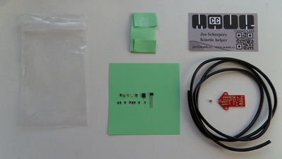
What`s in the bag
There is a small magnet in the bag, so be careful when you open it.
Content :
- ziplock bag
- Hall-O pcb
- paper containing components
- 1m cable
- magnet
There is a small magnet in the bag, so be careful when you open it.
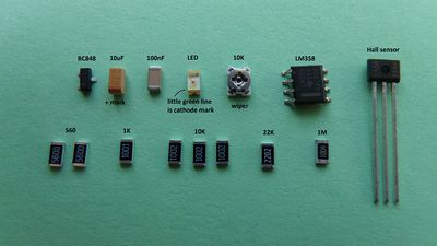
Content of paper
 Click on image for a larger format
Content :
- paper (color may vary)
- A1302UA linear hall sensor
- BC848 npn transistor
- 10uF capacitor
- 100nF capacitor
- green LED
- 10K potentiometer
- LM358 opamp
- 2x 560 resistor
- 1K resistor
- 3x 10K resistor
- 22K resistor
- 1M resistor
Soldering
First of all make sure your soldering iron has a tip of 0.4mm, and make sure its clean.
That part is so important, when soldering SMD, that I will repeat it: make sure the tip is clean.
Clean means, there is no rest tin on it, but also means that when you hold tin to it, the tin immediately flows. So without pressing the tin to the tip.
If it does not flow, cool the iron, and clean it with a knife. Do not cut but rather scrape the tip and then heat it back up while holding tin to it.
Now you have a proper working soldering iron.
When soldering SMD always start with the smallest components and work your way up.
Put tin on 1 pad on the board, place the component with tweezers and hold, solder that 1 pad and then the other(s).
The last component will be the hall sensor itself. Put the pins in the holes and bend the pins 90 degrees. Now the sensor is aligned with the board.
Cut the pins so they do not stick out on the other side(1mm)
Note that the sensor should stick out about 2 mm from the board, to ensure you can bend the sensor in a 90 degree angle opposed to the board.
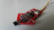
Now you are ready to go to the main Hall-Θ page, and assemble the rest of the Hall-O.

