Delta Rostock mini G2s
| |
Not Open Source
As stated in the RepRap Wiki Policy, a wiki page that describes a product offered for sale must provide source files for that product. This page is missing at least these item(s)
There might be more items missing. If you want to help improve this design, please find source files for these missing items and upload them to this wiki, or link to the repository containing them. In accordance with the Deletion policy, an admin will review this page in about three weeks to determine if it should be removed or not. If source files are not uploaded by the proposed delete date, this page will be removed from the wiki. Proposed delete date: {{{deletedate}}} Questions about this tag can be addressed on this page's discussion page or on the Administration, Announcements, Policy forum. |

This Rostock mini G2s is a companion piece of our new upgraded delta 3D printer -Rostock mini G2. G2s is designed to support dual extruder. With G2s you can print a single two-color object, or you can print two objects in one print job, each made from a different color. You can also print one single-color object, as with other single-extruder 3D printers. Or you can use one extruder for infill or support. The 2 extruder motor pushes filament through 2 head separately, so mixing colors printing is not applicable for the moment. This G2s is powered by our newly designed control system—GT2560 that supports 2 extruders and eliminates the complicated wiring of Mega2560+Ramps 1.4 and it is more space-saving. An auto-leveling auto-calibration device is also added on G2; which means you do not have to adjust it every time before you start printing, after the first assembly work, you can almost plug and play. In terms of printing filament, G2s not only support PLA and ABS, Nylon and wood filament is also available, which enables more possibilities to create 3D printing project. This G2s is also improved with LCD control panel; you can monitor the printing process in real time and with a SD card it can realize stand-alone printing, very convenient.
Contents
- 1 Main features:
- 2 Specifications:
- 3 BOM
- 4 Sources
- 5 Building Modifications
- 5.1 Always-on Hot End Fan
- 5.2 Enable Both Heatbed Coils
- 5.3 Improve Heatbed Insulation
- 5.4 Adjusting the Bed Levelling From The Top
- 5.5 Z-Probe Lock Ring
- 5.6 G2S J-Head Orientation
- 5.7 J-Head Teflon Guide Solution
- 5.8 Frame Tightness Solution
- 5.9 Incorrectly Threaded Smooth Rods Solution
- 5.10 Belt Jam at Idler Pulley Solution
- 5.11 Endstop Bolts Missing Endstop Switch Solution
- 5.12 Excess Slop on Rod Ends Solution
- 5.13 Repetier Firmware Configuration
- 6 Troubleshooting
- 7 set up
Main features:
- With dual extruder, support multiple way of printing.
- Support PLA, ABS, Nylon and Wood, giving more possibilities to create 3D printing project.
- New updated control system.
- Auto-leveling and auto-calibration.
- More flexible effectors and diagonal rods.
- More fluent printing process and higher precession.
Specifications:
Print Volume: 170 x 200mm
Chassis: laser -cut acrylic plate
The Layer Thickness: 0.1mm
Layer Resolution: 0.1mm
Filament Diameter: 1.75, 3mm
Nozzle Diameter: 0.3, 0.35, 0.4, 0.5mm
Print Speed: 60 to 120 mm/sec
Print Plate Size: 210 x 3mm
Print Plate (Build Platform): aluminum plate + heatbed
XYZ Bearings: carbon steel
Stepper Motors: 1.8° step angle with 1/16 micro-stepping
Max Heated Bed Temp: about 110 ℃
Max Extruder Temp: about 240 ℃
AC Input: 115V/1.5A 230V/0.75A
Output:DC12V/0-15A
No. of Extruders: 2
Connectivity (Interface): USB, SD Card
Electronics: Geeetech GT2560
3D printing Software: Repetier Host
CAD Input data file format supported: STL, G code
Client Operating System: Windows, Linux, Mac
Machine Dimensions: 320 x 320 x 870mm
Machine weight:9kg
Shipping box dimensions:495*395*195mm
Shipping box weight:10kg
BOM
download the BOM here Media:Delta Rostock mini G2 Package List.pdf
Sources
Download the .STL file for the printed part here
Building Modifications
The following are community provided modifications to the Geeetech Delta Rostock G2/G2S, and are not supported by nor approved by Geeetech. Use at your own risk.
Always-on Hot End Fan
This is the most essential modification for the G2/G2s models with PEEK hot ends.
Failure to perform this modification can lead to meltdown of the PEEK heads when printing ABS.
If you follow the Geeetech assembly instructions, the hotend fan will be attached to the PWM_FAN output of the GT2560.
When printing in PLA, the fan will be on, cooling the PEEK hot end cylinders.
When printing in ABS, the fan will not be enabled, and the PEEK hot end cylinder will reach 240C, and the heater block will melt out of the PEEK cylinder and drop onto the build plate.
To eliminate this issue, swap the FAN_1 (Extruder 1 fan) with the PWM_FAN (Hot end fan) connections on the GT2560. This will cause the hot end fan to be on at all times.
The community has determined that the extruder fans serve no useful purpose, other than to blow small bits of plastic out of the filament gear. It is perfectly safe to disconnect them, or use the cables for additional bed or layer fans.
Enable Both Heatbed Coils
Some shipped Geeetech Heat Beds are improperly wired, and will only run half of the heating coils.
To resolve the issue, you will need to solder a thick wire (or at least 2 Arduino jumper pins) across pads 2 and 3 on the heat bed.

Only pads 1 and 3 are connected, so the coil present between pad 1 and pad 2 is unpowered.
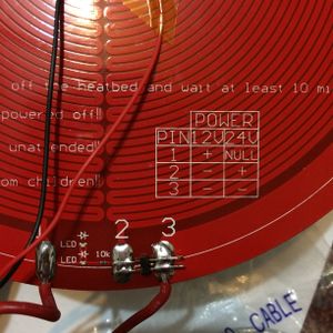
Some spare Arduino jumper pins soldered between pads 2 and 3 - both coils are now powered.


Improve Heatbed Insulation
A problem with the G2/G2s heatbed design is that air currents under heat bed can make it difficult to reach the high temperatures needed for ABS printing.
To solve that issue, you may want to add insulation to the heatbed.
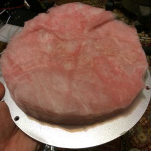
Using the aluminum bed plate as a template, cut a 200m circle of insulation (pink fiberglass is a good choice) that can be compressed down to 5mm in thickness.

Insulation in place - all heatbed heat will now go into the aluminum plate.


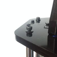
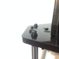
Adjusting the Bed Levelling From The Top
If you have especially slippery acrylic, you may find that the wingnuts may spin when you try to adjust the bed height via the recessed bolts in the bed.
If you have this issue, place a M3 "star" style lock washer (not included in the Geeetech kit) under the wing nuts, to prevent the wing nuts from spinning.
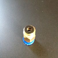
Z-Probe Lock Ring
If you have problems with the Z-Probe lock ring slipping, or are worried that your will strip the plastic threads in the lock ring while tightening the jam bolt, simply file a flat into the Z-Probe at the location where the lock ring will be.
Then, the lock ring will be unable to slip.
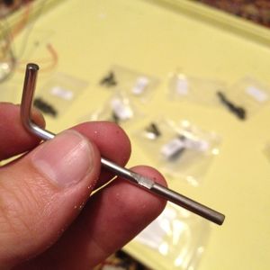
Z-Probe after the flat has been filed into it with a rectangular rasp.

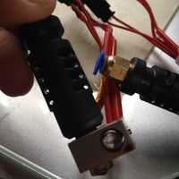
G2S J-Head Orientation
The G2S build documentation leaves the orientation of the J-Head up to the user. Many different orientations are possible.
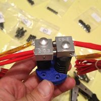
For balance (wiring feeds to both sides) and ease of maintenance (thermal block set screw accessible on both heads), use this orientation.
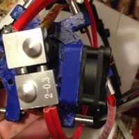
Unfortunately, the fan mount will be touching the lower J-Head in this setup.
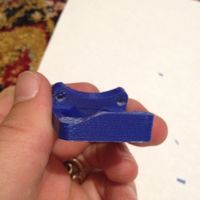
Trim down the interfering area of the fan mount with a craft blade.
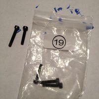
Replace the bolt for the modified mounting hole with a M3x16 (Bag 19, or hardware store)
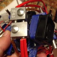
Final mount - note the 1mm~2mm gap between the lower J-Head and the fan mount.


J-Head Teflon Guide Solution
In some PEEK J-Heads, it has been observed that the Teflon filament guide it too short by approx 5mm.
This can cause a plug of plastic to develop between the Teflon guide and the heating block, and cause oozing of plastic between the threads of the PEEK cold side and the heating block. This oozing will create a ~4mm plug of plastic in the hot-end, and will gradually harden and caramelize, causing a very difficult to remove jam.
This problem can be resolved by adding a 2mm spacer (made of two M3 washers) at the top of the Teflon guide, and, as a side effect, also allows a 0.5mm gap between the PEEK cylinder and the heating block, improving cold end performance.
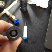
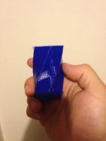
Plastic leaking between the teflon guide and the hot end - visible as the blue 'plug'
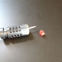
Caramelized plug removed from a jammed J-Head. This head had completely jammed when switching from PETG to PLA - the PLA/PETG mix hardened and could not be removed without reheating the J-Head and rapidly disassembling it.
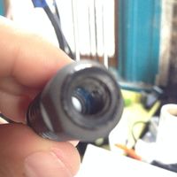
Teflon guide should be at the blue line - it's migrated up into the PTFE holder by about 5mm.
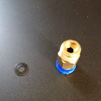
PTFE holder and M3 washer. The M3 washers can be found at a hardware store, or spares in Bag #5.
PTFE holder, M3 washer on top. Make a stack of 2-3 washers (total of approx 1mm to 2mm) to prevent the Teflon guide from pushing into the PTFE holder.
After heat-tightening, there should now be an approx 0.5mm to 1mm gap between the PEEK and the heat block, but there should no longer be leaks.


Frame Tightness Solution
If your frame is wobbly, the problem may be that the acrylic base plates are slightly thinner than specified.
To check, use a caliper to measure the thickness of the top and bottom acrylic base plates.
If they are in spec (8mm or slightly thicker) then do not perform this modification - your frame issues are elsewhere.
If your base or top acrylic plates are thinner (for example, in my G2S the base plate was 8mm, but the top plate was 7mm), you will be able to feel the end of the smooth rod slightly protruding through the acrylic, instead of inset, as required to stiffen the frame.
To resolve this issue, remove the suspect acrylic plate, and replace the single M8x1mm washers on the smooth rod ends with either two M8x1mm washers, or a single US 5/16th" x 1/16th" (approx 8mm x 1.5mm) washer. Note that all of the washers for the plate must be identical.
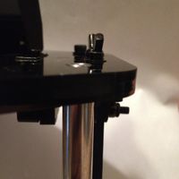
Note the smooth rod slightly protruding above the acrylic.
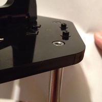
After the washers have been replaced, the rod is slightly inset, to allow the frame to be tensioned to the rod by the retaining bolt and washer.


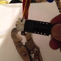
Incorrectly Threaded Smooth Rods Solution
In some instances, the smooth rods' 4mm end threads are too shallow by a few mm, due to variation of manufacture.
In this case, you will be unable to fully finger-tighten the 4mm bolts into the rods.
If this occurs, use the spare 4mm washers in Bag #6 to bridge the gap.
Do not attempt to over-tighten the 4mm bolts - if they can not be fully threaded, it is because they have hit the end of the blind 4mm hole - it is physically impossible for them to be tightened down any further!
As seen here, the 4mm thread is not properly manufactured in the smooth rod, and the 4mm bolt will not fully seat.
4mm washers added, now the bolt can be tightened properly.


Belt Jam at Idler Pulley Solution
If you are getting jams at the Idler Pulley, first verify that:
- The idler retaining bolt is fully tightened - if not, it can back out when the wingnut on the idler pulley is tightened, and jam against the belt.
- The idler retaining wingnut is fully tightened - if not, the idler pulley can end up at a slant, and the belt will jam against the idler pulley holder.
- The belt is fully inserted into the carriage belt retainer - if not, the belt will angle towards the idler pulley, and can jam against the idler pulley retainer.
If you have checked all of those and still have issues with belt jams, print out this File:Delta Rostock mini G2s MOD idlerpulley guide.stl (originally from Thingiverse user Gidim) 6 times, and insert it on the idler pulley bearings, between the belt and the idler pulley housing.
They should take under 3 minutes to print at 0.3mm layer height and 25% infill, if you print all 6 of them at a time. If you have issues with stringiness or other quality issues, print as many as you can fit on the bed, and pick the best 6 to use.
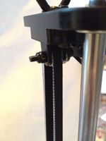
Belt that tended to jam, due to being unable to fully insert the belt into the carriage belt retainer.

Idler pulley guides installed - no more jams.


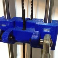
Endstop Bolts Missing Endstop Switch Solution
As the G2/G2s "wears in", the endstop bolts may begin to miss the endstop switches, as the hex retaining area in the carriage under the spring wears out - this will cause homing failures, and excessive belt wear.
To correct this, remove the spring from the endstop bolt, and use the 3mm hex holder on the carriage to retain the bolt.
After this modification, the endstop bolt will no longer have any slop.
NOTE: As with all endstop modifications, you must recalibrate your tower endstops:
- Run G28 to home to endstops
- Run G131 to clear tool offsets (temporarily)
- Run G84 to disable steppers motors
- Place a ruler (at least 200mm) under the carriage, on top of the smooth rod washer.
- Move the carriage down to the ruler
- Repeat this with the other two other axes
- All carriages are now at an equal height
- Run G132 S1 to home, and count offset steps, and save to EEPROM
WARNING: You must verify proper endstop switch electrical operation (using M119) before this modification! Failure to do so will result in damage to the endstop switch, as there will no longer be any vertical "springiness" at the homing position.
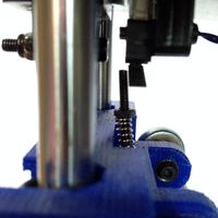
Spring-based endstop missing the endstop switch - the spring has 'broken through' the PLA of the carriage into the sparse infill inside.
After removing the spring, tighten the nut until it is 0.5mm under the surface of the carriage - do not tighten any further.
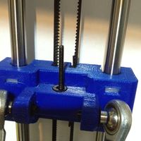
Cover the nut with a M4 washer from Bag #6.
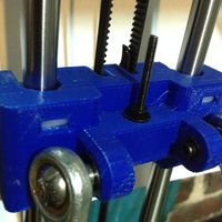
Tighten an additional M3 nut on top of the washer. Do not over tighten! - If you over-tighten, and break the bolt head through the lower PLA of the carriage, disassemble, and put a M4 washer, topped with a M3 nut, on the bolt head.
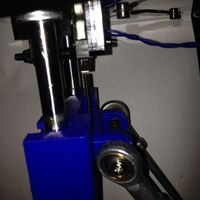
Fixed endstop now hits the endstop switch lever reliably.


Excess Slop on Rod Ends Solution
Some shipments of the G2/G2s have an incorrectly manufactured "Item 3, Rod-end bearing holder, D6.5 23mm" - the shipped product is 24mm, not 23mm.
This variance causes a slop of ~0.2mm at the rod ends, and >3mm of movable slop in the spider effector itself.
To eliminate the slop, there are three options:
- Contact Geeetech Technical Support for the correctly manufactured parts.
- Purchase 6mm ID, 8mm OD, 0.2mm or 0.5mm shim washers (if you can source them)
- Print this File:Delta Rostock mini G2s MOD rodendshim washers.stl set of shim washers.
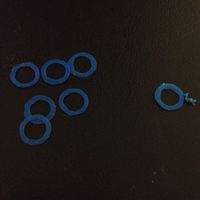
Set of washers, printed out. Separate and discard any with inside-diameter defects, or that are thinner than 0.2mm, or thicker than 0.5mm. You will need 12 washers total.
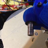
Rod-End Bearing Holder - Spider End. There is an identical bearing holder on the other end of the rod. Both holders will need the shims.
Push the shim washer over the rod end bearing holder. It should seat next to the ridge of the bearing holder.
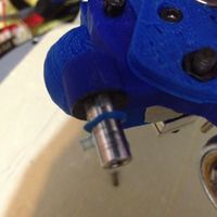
Properly shimmed rod end holder, with rod end attached. 0mm of slop measured.
Repetier Firmware Configuration
This is my (User:Ezrec's) first cut at a Repetier firmware config (0.91).
NOTE: If your Z Probe has any side to side or back to front wiggle, do not use autoprobing! Your head will tilt and slide all over the place, and you may damage your nozzle.
NOTE: This firmware config was built for a RAMPS 1.4 hardware, and has not been tested on the GT2560 controller. Use at your own risk.
Firmware config for Repetier 0.91: File:Delta Rostock mini G2s MOD Repetier 0.91 Configuration.h.
This configuration file has the full JSON config in it, so feel free to feed it back into Repetier's web-based configuration generator to build a firmware for a different version.
Troubleshooting
J-Head Leaks
If plastic oozes out between the PEEK cold region and the metal hot end, you may need to heat-tighten the J-Head.
First, a note of warning - until you have verified and calibrated the operation of your hot end/thermistor combination, DO NOT SET THE EXTRUDER ABOVE 200C.
Without the active cooling fan, the PEEK cylinder could begin to melt at approx 240C. If you are using the default hot end fan connection to PWM FAN, you can easily exceed the melting point of the PEEK cylinders if you set the hot-end temperature above 220C. To be safe, set the hot end to at or below 200C.
Since PEEK slightly expands when heated, if the J-Head was too cold when initially assembled, the PEEK threads will loosen once the PEEK reaches target temperature, and will allow plastic to ooze out between the threads.
The solution is as follows:
- Heat the J-Head up to approx 200C (using your G-Code sender, RepetierHost is what Geeetech suggests), and let it "soak" at 200C for approx 5 minutes.
- Using a vice-grip on the metal heater block of the J-Head (making sure not to clamp onto the nozzle!), loosen the heater block by a quarter turn
- Wipe off any excess plastic from the heater block and PEEK cylinder with a dry paper towel.
- Be careful not to wipe the nozzle - you can easily plug up a 0.3mm nozzle with paper fibers.
- Tighten the heater block to a snug fit.
Do not over-tighten the J-Head! A snug fit is all that is needed - too much force will break the PEEK threads and destroy the head.
NOTE: For the G2s model, you may need to disassemble the spider's J-Head holder to be able to loosen and tighten the heater block.
Although the top of the PEEK cylinder is cool to the touch, the bottom is very hot. Use a vice-grip to hold it while tightening.

G2s Misaligned Hot Ends
If you are getting prints on a G2s where the second J-Head's nozzle tip is hitting your print, then the one of your hot ends needs to be tightened.
This is especially visible on spiral-vase prints, and a spiral vase is a great object to use for this type of calibration. Make sure to have both J-Heads heated, so that you can see a blemish, instead of the interfering hot end causing a mechanical jam!
If your left J-Head nozzle is hitting the print while the right J-Head is extruding, tighten your left J-Head's hot end 1/8th of a turn.
If your right J-Head nozzle is hitting the print while the left J-Head is extruding, tighten your right J-Head's 1/8th of a turn.
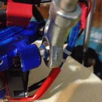
If adjusting the hot-end is not able to eliminate the interference, add a 4mm washer (Bag #6) between the top retaining bracket and spider, where the 4mm bolt passes through. If the front J-Head is interfering, add a 4mm washer to the front, and if the rear J-Head is interfering, add a 4mm washer to the back.
Spiral vase print with a blemish. Note the glob-line where the non-printing extruder's hot end interfered with the part on every pass.

set up
for detailed set up instruction, you can see at here.