DC digital servomotor
-- Main.AdrianBowyer - 26 Jan 2006
Contents
DC Digital Servomotor
1. Introduction
At the RepRap project we have a never-ending discussion about the relative merits of stepper motors (simple, implicitly digital, but low torque and expensive) and DC motors (more complicated to control, but high-torque and cheap). This small discussion mirrors a much larger one that has been going on for years in the machine tool and robotics industries. It hasn't been resolved there, so we probably won't arrive at a definitive answer either.
To start with, RepRap will most likely use steppers, as we don't need a lot of torque (additive manufacturing is inherently very low force) and their simplicity of control cuts down on electronics - a big bonus.
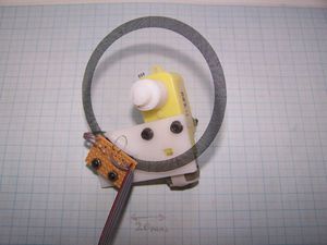
However, I though I'd see if I could make a very cheap and simple DC digital servomotor using rapid prototyping. This page describes it, and this is the finished device:
2. Requirements
I decided to use the same geared motor that I used for the Mark II Polymorph extruder, as it is sturdy and very low cost. I also decided to use a slotted wheel and optical switching for detecting rotation, and further that the wheel should be printable using an everyday inkjet printer on the acetate sheets intended for overhead projectors. Finally I decided that to go for a resolution of 400 steps per revolution. That is the same as the steppers that Ed Sells and I are using for the first cartesian axes for RepRap.
3. The Slotted Wheel
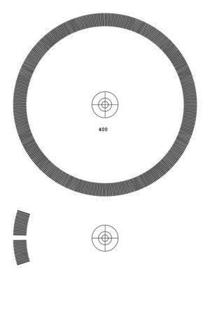
I wrote a C++ program to generate wheel patterns (I'll translate it to Java for the final version, as that is the language that we've decided to use for RepRap). It produces images like this:
The original is much higher resolution. The complete wheel is the part that rotates with the geared-down motor shaft; it has the number of slots (400) written on as a reminder, and a centre mark to make it simple to punch a hole to attach it to the shaft.
The segments at the bottom are interference patterns. The top one is in phase with the big wheel. The bottom one is π out of phase. These are placed on the shaft as well to get the alignment right, with the two patterns over two stationary LEDs. The patterns are then glued to the LED supports and the rest of them is cut away and discarded.
The wheel rotates over the stationary patterns above the LEDS and the stripes go in and out of phase. Above each LED is a photodiode, and each sees a 400 cycles-per-revolution signal as the wheel goes in and out of phase with the stationary patterns. The patterns' phase difference allows the direction of rotation to be determined.
The whole pattern is simply imported into a document as an image, drag-scaled to make it about 80mm in diameter (this doesn't need to be fabulously accurate), printed on an acetate sheet, and cut out with a pair of scissors.
4. Electronics
The first problem that had to be solved was that inkjet printer ink is transparent to infra-red light. Almost all photodetectors and emmitters work with IR, and so are cheap because of quantity; but they were all useless because of the transparency.
However, when the motor turns you can see the light and dark flashes as the pattens go in and out of phase, so clearly the human eyeball can pick up the signal. Human sight has a peak response in the green (evolutionary pressure in a world painted by green chlorophyll), so I went for an ordinary green LED and a photodiode attuned to human visual response (the Aglient apds-9002).
The photodiode is an SMT device, which made soldering it a bit tricky. It also doesn't have a big frequency response, which may turn out to be a pain if the motor goes fast.
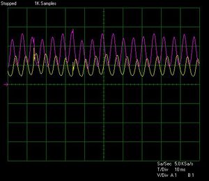
However, the signal out of the scope was gratifyingly clear:
Note the difference in phase between the two signals. The purple one is slightly higher amplitude - I think because I got its photodiode slightly better aligned with its corresponding LED. Also, both signals have a DC component (0V is where the purple arrow at the left is). I think this is daylight, so it may be necessary to do a bit of a re-design to put the detectors in camera.
5. Future Developments
I'll build a PIC controller for the thing, program it up, and see how it goes. Assuming it can be made to work reliably (i.e. not to miss steps and to position to within a single step; note the occasional kiss of noise on the scope traces) I'll write up the full design and post it here on the Wiki.


