DC Motor Driver 1 0
Contents
DC Motor Driver v1.0
Overview
<div class="thumb tright"></div>This board allows you to control up to 2 small DC motors individually. Each motor can be driven at a maximum of 750 mA. It supports both direction and speed control. It is designed to be interfaced with a microcontroller such as the Arduino, or even something like a Basic Stamp. Whatever you can choose, it should be able to work with this board as it has a simple and easy to use interface.
- You'll need a soldering toolkit to do most of this.
- Read our Electronics Fabrication Guide if you're new.
Files
You can download the release file from SourceForge that has a bunch of helpful files for this board. It contains:
- GERBER files for getting it manufactured
- PDF files of the schematic, copper layers, and silkscreen
- Eagle source files for modification
- 3D rendered image as well as POVRay scene file
- exerciser code to test your board.
Interface
Input
The PWM Driver has 5 input pins:
| Pin | Function |
| POWER | This is a power input connector. We use a polarized disk-drive style power connector found on nearly every ATX power supply in existence. If you want to directly connect your own power, the board required 12v input. |
| GND | It's recommended to connect this to the ground on your Arduino to share a common ground. |
| DIR_A | This pin controls the direction of the motor controller. A high signal tells the motor to rotate forward, and a low signal tells the motor to rotate backwards. The actual direction depends on how you have your motor wired up. |
| PWM_A | This pin controls the speed of your motor's rotation. You need to supply it a PWM signal, which determines the speed. |
| DIR_B | This is identical to DIR_A, except it controls the second motor. |
| PWM_B | This is identical to PWM_A, except it controls the second motor.
|
Output
Each motor output is rated for up to 750 mA. If you wire up a motor that draws more current than that, you risk blowing out the L293D. If you plan on doing this, its suggested you socket the L293D so you can easily replace it, should overheat and fail.
| Pin | Function |
| channel a/b | This is the output for the respective motor input pins. Each output has two pins: depending on the direction the motor is being driven, the polarity will change. You will need to experiment to determine the proper way to wire your motor up to get it to rotate in the correct direction. There are only two possibilities, so don't worry. =) |
Circuit Board
<div class="thumb tright"></div>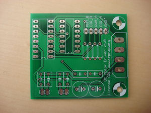
You can either buy this PCB from the RepRap Research Foundation, or you can make your own. The image above shows the professionally manufactured PCB ready for soldering. Its also cheap, only $3.50 USD.
Components
Refer to the part list generator for information on where to get the stuff you need.
<iframe width='100%' height='300' frameborder='0' src='http://spreadsheets.google.com/pub?key=pmEMxYRcQzzATwbOb71BmGA&output=html&gid=25&single=true&widget=true'></iframe>
Known Bugs
These are all the bugs we know about. If you find any, please contact us in the forums.
Silkscreen Oops
We forgot a couple layers on the silkscreen, and neither the part names, or their values are present. You'll have to refer to the pictures, the PDF in the release files to determine what parts go where. Its pretty simple to figure out though. There are only 6 different types of components to assemble, and it is very easy to see which parts go where.
Build Process
R1-R4
Solder the resistors to the board. They are all 100 Kohm resistors, and the orientation does not matter. Make sure to clip the component leads after you have soldered them into the board.
L293D
This is the motor driver chip. Match up the dimple on the top of the chip with the silkscreen. This orientation is important. Take care not to bend any chip legs. This chip goes into the place with the most pins.
74HC00N
This is the logic chip. Match up the dimple on the top of the chip with the silkscreen. This orientation is important. Take care not to bend any chip legs. This chip goes in the other spot for IC's.
Motor Connectors
Solder the motor connectors here. Face the connector tabs toward the inside of the board. Make sure they are flush with the PCB and then solder them in.
Power Connector
This is the 4 pin connector that has 2 angled sides inside the connector. Match up these sides with the silkscreen and solder the connector to the board. This is where you will hook it up to the power supply.
C1-C6
These are the 100nF (0.1uF) ceramic capacitors. They all fit into the rectangular silkscreens. The polarity doesn't matter with these components, so just put them in and solder them. Clip the legs close to the board after you are done.
C7, C8
These are the 100uF ceramic capacitors. These have a specific orientation, so make sure you insert them the right way. The board has a + sign near one hole, and the capacitor has a - sign along one side to identify it. Make sure you insert the insert the component accordingly (- lead goes into the - hole)
Test Your Board
Now we have to test the board. Its very easy, and consists of a few steps.
Connect Power to Board
Always turn your power supply off before plugging it in. It won't fry things most of the time... but all it takes is once to damage things.
Simply take your hacked PC power supply and plug a power connector into board. There is no power indicator, but as long as nothing starts smoking, you should be fine.
Turn your power supply off while you plug boards together!
Wire up test devices
You will want to wire up two motors to the board to test both channels. If you only have one motor, you can still test it, but you'll have to test them each individually. The orientation of your motor doesn't matter, as long as it can be driven in both directions, and it pulls less than 750 mA of power.
Connect Board to Arduino.
This part is very easy. Strip 1/4" from the end of the input wires (You used Cat6 ethernet innards right???) Now, insert the end of each input into the correct pin on the Arduino, and then connect the Ground pin to Ground on Arduino. Use the table below to determine what pins to hook up to what:
| PWM Pin | Arduino Pin |
| GND | Ground |
Upload Firmware to Arduino
Now, feel free to turn on the power to your power suppply. Next, open the Arduino software, and upload the files located in the /exerciser directory in the file that you downloaded above. After the firmware has compiled and uploaded, the Arduino will restart and the exerciser will begin shortly.
The basic way the motor exerciser works is this:
- Both motors will rotate in opposite directions.
- Both motors will gradually speed up to maximum speed.
- Both motors will gradually slow back down to a stopped state.
- Both motors will then switch directions and repeat the program.
Troubleshooting
- First, check to see that you have supplied power to the board.
- If that doesn't work, check that you have the board wired up correctly to the Arduino.
- If the motors do not move at all, then check your circuit for shorts and dry joints.
- If only one motor turns, or they turn in the same direction, check the orientation of how the motors are wired.