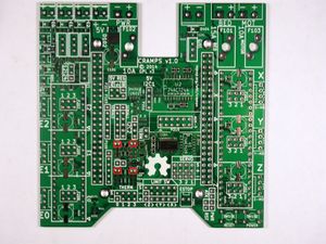
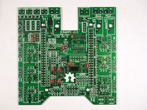
CRAMPS1.0
Release status: Working
| Description | Cape-RAMPS for BeagleBone
|
| License | GPL
|
| Author | |
| Contributors | |
| Based-on | |
| Categories | |
| CAD Models | KiCAD
|
| External Link |
Contents
- 1 Summary
- 2 Safety
- 3 Assembly
- 3.1 Required Tools
- 3.2 Cape Assembly
- 3.2.1 Do Not Populate : Remove
- 3.2.2 Do Not Populate : Optional
- 3.2.3 Fine Pitch SMT
- 3.2.4 Surface Mount Parts
- 3.2.4.1 C1 C2 C102 C207 C305 C502 C503 C504 C505 C601 : 100 nF 35V 0805 Capacitor
- 3.2.4.2 C301 C302 C303 C501 : 10 uF 10V 0805 Capacitor
- 3.2.4.3 R701 R702 R703 R704 R901 R902 : 220R 0805 Resistor
- 3.2.4.4 R101 : 330R 0805 Resistor
- 3.2.4.5 R301 R302 R303 R501 : 1k0 1% 0805 Resistor
- 3.2.4.6 R905 R906 : 1k8 0805 Resistor
- 3.2.4.7 R219 R220 R221 R222 : 2k7 0805 Resistor
- 3.2.4.8 R304 R305 R502 R503 R504 R505 : 4k7 0805 Resistor
- 3.2.4.9 R1 R2 R211 R212 R401 R402 : 10k 0805 Resistor
- 3.2.4.10 R201 R202 R203 R207 R208 R210 : 100K 0805 Resistor
- 3.2.4.11 D101 : Green 0805 LED
- 3.2.4.12 D201 D202 D203 D204 D901 D902 : Red 0805 LED
Summary
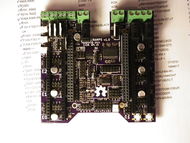
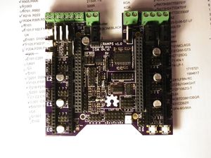
The CRAMPS board is a mixed surface-mount and through-hole design. There are a small number of fine-pitch components (the resistor networks and FET bus level translator). These parts are challenging but possible to solder by hand. All other parts are large pitch or through-hole, and are relatively easy to hand solder.
Safety
The CRAMPS board is designed to handle power levels capable of causing a fire. Be very careful with the initial board checkout, ideally using a power supply protected from short circuit and overload. Never operate your board unattended, and make sure all connected parts subject to heating (including the wires and connectors!) are far away from any potentially combustible material. Always use the proper fuses, and insure your smoke detector is working properly.
Assembly
Required Tools
- You must have
- Solder iron, solder wire, good tweezers
- You really need
- Solder wick, solder sucker, flux pen
- Optional methods use
- Solder paste, hot plate or oven
Cape Assembly
Soldering the CRAMPS board includes both surface mount and through hole soldering.
The surface mount can be done a few ways. To hand solder, start by putting a small amount of solder on one pad. If you have flux, coat the soldered pad. Use the tweezers to hold the component down in position and heat the solder to tack the component into place (make sure the entire solder blob flows so you don't get a cold solder joint). Then solder the other pads. Also popular is using solder paste for pad by pad soldering, Oven Reflow (need link), and HotplateReflowTechnique
Solder the SMT components first, starting with the fine pitch parts then working through the parts from shortest to tallest. Then solder the through-hole parts on top of the board. Finally solder the pin headers on the bottom of the board.
Do Not Populate : Remove
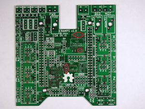
Initial testing showed that the thermistor protection diodes were not needed and caused issues with performance. These parts should not be populated, and should be removed (or have one terminal lifted) if present on the board. I recommend drawing across the pads with a Sharpie or similar permanent marker so you know these parts should not be present.
- 1N4148 : D1001 D1002 D1003 D1004 D1005 D1006 D1007 D1008
Do Not Populate : Optional
These parts are not required, but do not need to be removed if you have already soldered them to the board. I recommend drawing across the pads with a Sharpie or similar permanent marker so you know these parts should not be present.
- D102 : SS10P4-M3/86A
- U1001 : TLV431CDBZR
- R1002 : 1k 1% 0805 Resistor
- R1003 : 2150R 1% 0805 Resistor
- R1004 : 12k4 1% 0805 Resistor
Fine Pitch SMT
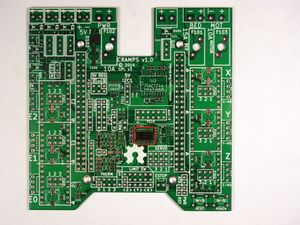
RP1 RP2 RP3 RP801 RP802 : 10K Resistor Network
These can be placed in any orientation.
U5 : 74CBTLD3861 - FET Bus Level Translator
Place with pin 1 aligned with the silk-screen notch on the PCB.
Surface Mount Parts
C1 C2 C102 C207 C305 C502 C503 C504 C505 C601 : 100 nF 35V 0805 Capacitor
These can be placed in any orientation.
C301 C302 C303 C501 : 10 uF 10V 0805 Capacitor
These can be placed in any orientation.
R701 R702 R703 R704 R901 R902 : 220R 0805 Resistor
These can be placed in any orientation.
R101 : 330R 0805 Resistor
These can be placed in any orientation.
R301 R302 R303 R501 : 1k0 1% 0805 Resistor
These can be placed in any orientation.
R905 R906 : 1k8 0805 Resistor
These can be placed in any orientation.
R219 R220 R221 R222 : 2k7 0805 Resistor
These can be placed in any orientation.
R304 R305 R502 R503 R504 R505 : 4k7 0805 Resistor
These can be placed in any orientation.
R1 R2 R211 R212 R401 R402 : 10k 0805 Resistor
These can be placed in any orientation.
R201 R202 R203 R207 R208 R210 : 100K 0805 Resistor
These can be placed in any orientation.
D101 : Green 0805 LED
Place with the cathode terminal (marked with a small dot) closest to the E0 Pololu socket.
WARNING The Red and Green LEDs are marked differently!
D201 D202 D203 D204 D901 D902 : Red 0805 LED
Place with the anode (marked with a small dot) away from the pad marked with a silkscreen line.
WARNING The Red and Green LEDs are marked differently!
