Builders/Frank
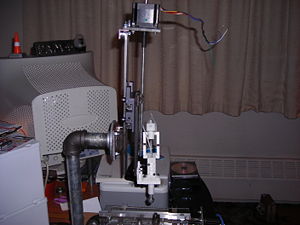
Frank is the name of the RepStrap built by Stanley Ames (Demented Chihuahua) in 2007-2008.
Contents
Build Breakdown
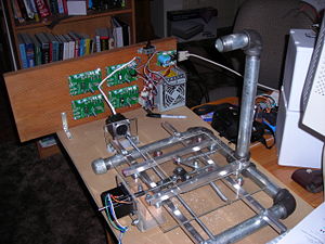
Frank was built in many stages over roughly a 10 month period which started in the summer months of 2007. He is a McWire Cartesian bot that uses the RepRap Gen 1 electronics and an Mk II extruder. Standard 200 step stepper motors from the RRRF were used and cat5e cabling was used for all the wiring. A 300 watt pc power supply runs all of the electronics and stepper motors. Limit switches, standard opto-endstops, were used for the home positions only and not for the max positions as that is really handled in the preferences page of the RepRap host software.
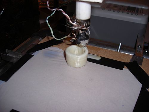
Frank became functional on Friday, April 18, 2008 with the printing of a minimug in fine RepRap style.
Frame
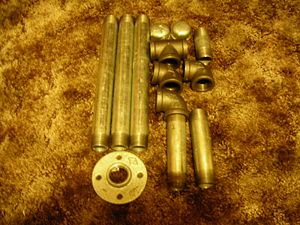
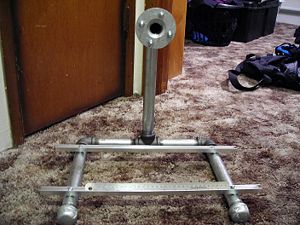
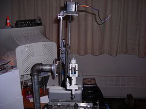
Frank's frame is a McWire design built from 1" steel water pipe and fittings. The frame is bolted to a piece of MDF for stability. None of the joints are locked in place with anything other than friction. I haven't had any problems with stability even though there was no milling on Frank. In addition, having the movable head allows me to pack Frank around to various places in order to show him off conveniently.
Mistakes
- Used one inch pipe when really 1/2 would have been fine and much cheaper.
Axis
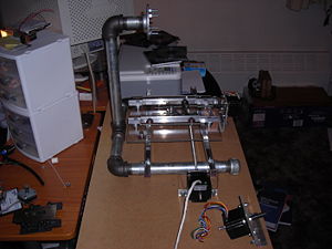
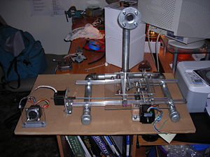
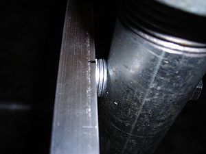
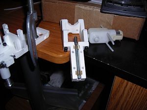
The x and y-axis of Frank use the original McWire design. Pictures are worth a thousand words so here are six thousand equivalent words...
X-axis
Y-axis
Z-axis
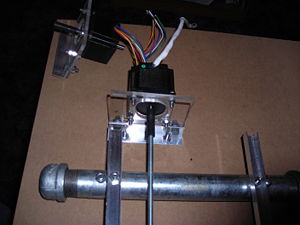
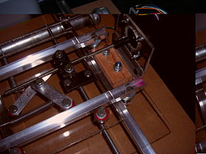
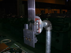
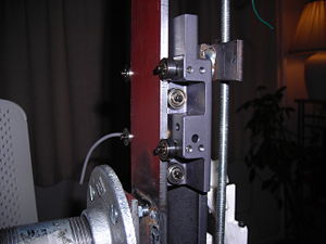
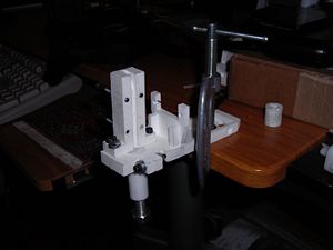
The z-axis makes use of a unique piece of scavenged equipment I call The Slider from a universal stereo plotter. The Slider moves on a piece of plate steel I call The Vertical. The Slider clamps The Vertical on either side and on the front face. The Slider holds itself in this position by use of magnets that hover just above the front face of The Vertical and are attached to The Slider itself. This is hard to visualize so here are some pictures.
Mistakes
- I Tried to use closet door rollers instead of 608 bearings.
- Result was not successful. Don't try the door rollers, but do try other things as this is an area that can be improved.
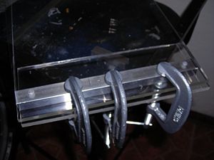
- Bought a piece of plexi glass for the stages.
- This is just unnecessary. Use MDF instead. It costs less, is more workable, and you won't worry about marring it because it's cheaply replaceable.
- I used 1 inch pipe.
- Use 1/2 pipe. It is plenty strong/stiff enough and costs far less. Save yourself some money.
- I used 12 inch segments as my longest segments.
- This just isn't long enough for a good print volume. Use longer segments. Think 12" for the two short tubes on the bottom of the frame and 16" segments for the two long tubes on the bottom. This will give you a much expanded print volume.
- I used a 3 inch segment go connect the bracket to the vertical.
- Remember that the distance between your extruder tip and the vertical of the frame is the maximum print distance for your y-axis. The distance between your extruder tip and the back of the frame needs to be equal to the distance between your extruder tip and the front of your frame so that you maximize your print distance.
Electronics
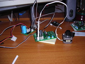
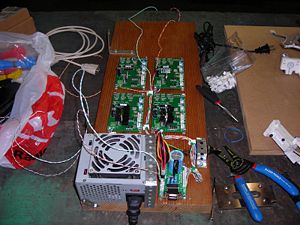
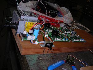
Frank uses the following electronics:
- Pic Based Gen 1 electronics
- Universal Controller boards (4) v1.2.1
- Power Communication board (1) v1.3
- Opto-Endstop boards (3) v1.0.1
Mistakes
- Didn't test the electronics fully before mounting them on their board.
- Test Test Test! Why, oh, why didn't I test fully!? Stupid of me. Run through all the suggested tests before you commit to any mounting of electronics. Otherwise your electronics look like a rats nest before you ever get it running and it stays that way.
- Didn't buy extra headers and assorted connection hardware.
- Those two pin, three pin, and four pin headers and the bits that go with them are invaluable. Buy about 3 times what you will need. This allows you to make a wiring test-harness for full electronics testing and still have enough left over so that you can make a "final" electronics assembly that will look good and do you proud.
- Hard wired one of the motors, all the opto-endstops, the heater, the thermistor, and the extruder pump into the driver cards.
- This amounted to guaranteeing that I would have to desolder a bunch of junk before being able to swamp things out or run any major tests. Stupid of me. I later bought screw terminals for everything and never ran any wires directly from one device to another. There is always a way to disconnect things. In my case there are now about three ways to disconnect things which makes my life a bunch easier. Hard learned lesson.
Firmware
Frank is currently loaded with the V1.2_fullstep_all PIC firmware. I'm fairly pleased with what Frank can do with the older PIC electronics. I was planning on upgrading to the newer Arduino electronics but now I'm not sure if this is my best course of action. I'm not really convinced by the reasons given for abandoning the PIC line of development for the Arduino and think an effort should be made to continue the PIC line. More thoughts to come on this.
Mistakes
No real mistakes here. Just burn the chips and go!
Extruder
The extruder was a huge hassle for me. Not only did I have the usual bits of trouble but I made such stupid mistakes as to give myself an entire new class of troubles! Don't repeat my mistakes.
Mistakes
- Didn't take time to find proper bolts for the extruder body.
- This caused all sorts of havoc and a range of problems occurred: the body slopping back and forth, loosening nuts, too tight a fit. Don't do this, it sucks!
- Didn't use washers.
- This was just stupid haste. I wanted to see something work and this caused a bit of trouble in getting things tight, loose, and lining up. Stupid and hasty.
- Didn't use pipe clamp on PTFE.
- About 5 minutes into my first extrusion, my heater popped out of my PTFE and started burning my y-axis print platform, and madness ensued. Avoid this if at all possible.
- Didn't drill holes through PTFE Clamp and PTFE for bolts to hold it in.
- This wasn't really my fault as this innovation hadn't been thought of yet. After I modified my assembly to include this, I had zero problem with the heater and PTFE assembly popping out of the clamp. Worked like a champ.
- Didn't insulate my heater barrel.
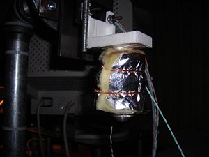
- This didn't cause any real problems, but it did cause me to have to twiddle my thumbs waiting for the heater to get to temp. Insulate with a piece of fiberglass insulation and wrap with some wire. This has the added benefit of keeping your heater wires and thermistor wires from moving about, possibly shorting, or breaking.
- Used Offset drive for extruder.
- Kept snapping off at the joint. Horrible design. Stay away from it. Instead, go with the direct drive model. Much better. Never had a problem with it.
- Made my own drive screw (I cut the threads myself on a lathe)
- 10-32 threads in stainless steel are a bit small to cut yourself on a lathe. Just buy 10-32 studding from McMaster or buy the whole extruder in a kit and save yourself the trouble. I'm still using my screw but would have saved hours if I hadn't.
- Didn't test the extruder before mounting it to the machine.
- Test Test Test! Clamp it to a table and run about an hours worth of extrusion through it. This allows you to work out the major kinks before you mount it and things get hairy to get to. Seriously, Test Test Test!
- Didn't buy about 5 extra heater barrels and PTFE segments for myself.
- Seriously, these are the pieces you will go through the most of...buy many of them. I was relying on my school connections to machine them--simple tap and such--but I really needed to buy the tap myself and be able to make them on my own since I ended up going through 4 of them! Buy many and tool up to keep making them. If we do anything on this project that is valuable, it needs to be a new heater barrel design.
Calibration and Testing
This section isn't really about RepStrap Frank but about RepStrap FrankNuvo, the refurbished RepStrap Frank. I've taken my time while fixing Frank up into his better, prettier, and more functional FrankNuvo self. Previously I kind of did the seat of my pants calibration method--being young and dumb--and while this provided almost immediate results, it wasn't near the quality Frank was capable of.
This is a rather big-ish section so I want to break it down fairly far to deal with what I do now to get a Gen 1 Strap up and running.
XAxisScale(steps/mm), YAxisScale(steps/mm), ZAxisScale(steps/mm)
First I had to set my Steps/mm settings in the Globals section of the Preferences page. This involved a slight bit of calculations. I have 200 step motors and I use 1/4-20 threaded rod. That means for every inch I travel I have to go through 4000 steps (200 * 20). Dividing this by the number of millimeters per inch (25.4) gives us (4000/25.4) our steps per millimeter as required for the preferences page. Mine came out to 157.4803 so that's what I put in the XAxisScale, YAxisScale, and ZAxisScale preferences.
Extruder0_XYSpeed(0...255) and MovementSpeedZ(0...255)
Second I had to find the proper speed for my steppers to be driven at. I did this by simply moving the slider in the Stepper Exerciser box and then playing with the speed until the motors ran quietly, smoothly and consistently. I found the settings to be 148 for my x/y-axis and 143 for my z-axis. I set the Extruder0_XYSpeed(0...255) in the Extruder0 tab to 148 and the MovementSpeedZ(0...255) in the Globals tab to 143.
WorkingX(mm), WorkingY(mm), WorkingZ(mm)
Next is setting up the limits on FrankNuvo. I went with the three Opto setup up so I do not have max-limits. This means I need to take some care in setting my WorkingX, WorkingY, and WorkingZ under the Globals tab of the Preferences page. To do this I used five ruber bands, a bic pen, and a piece of paper. I used the rubber bands to strap the bic pen securely to the extruder. After it was attached, I taped a piece of paper to my print platform. I then lowered my z-axis till the pen was firmly pressed against the paper, but not too firmly or it would skip.
I fired up the Stepper Exerciser and drove my x-axis to it's max position manually by moving the slider a little bit at a time. After it was at the position I decided would be it's max--150 mm--I drove the y-axis to its max in the same manner--115 mm--I then homed x-axis and then the y-axis to make myself a box on the paper.
This gave me a chance to check several things about FrankNuvo that are interesting. Does he draw straight lines? Are his horizontal and perpendicular lines orthogonal to each other? Are my steps/mm settings correct--ie. are the lines the lengths they should be according to the step count in the Stepper Exerciser? Accordingly I took a square, a set of Starrett calipers and a critical eye to the rectangle that FrankNuvo drew. Turns out I did things correctly. All the parameters we just listed came out correct. Frank is a straight line machine capable of drawing true orthoginal lines at least to the scale limits offered by a bic pen and measurable by a good set of Starrett 797 calipers. Hope he is fully capable in all other areas too!
Having found the correct numbers for my WorkingX and WorkingY I fudged a little bit and put in a reasonable number for my WorkingZ. I put my z-axis in the furthest up position it could have and used a regular old steel ruler to find the distance form the tip of the extruder barrel and the print stage. I then chose a number one cm smaller to account for the inaccuracy of the measurement method and for expansion of the PTFE barrel when it gets hot. This gave me a distance of 12 cm or 120 mm.
Extruder0_hb(C) and Extruder0_hm(C/pwr)
Finally, we get to setting up the extruder! First off is running the Heater Profiler tool. Since I'm running Gen 1 electronics, I have to set the Extruder0_hb(C) and Extruder0_hm(C/pwr) settings. This requires that I run the Heater Profiler, collect the output from the command window--the power level and the temp it reach at that power level--and run a Simple Linear Regression on it. To do this, I used this site: http://www.wessa.net/slr.wasp. The format was easy, power level in the x column and temp in the y column, and you simply had to read the chart at the bottom to find your hb number--corresponding to the y-intercept in the equation--and hm number--the x term coefficient in the equation on the graph. In my case these were -27.6047 and 0.96203 respectively. Keep in mind this takes a bit of time to run--maybe 45 minutes in my case--so schedule a block of time for yours.
Tensioning the Extruder Halves Then came the hard part, tensioning the extruder body halves using the springs and nuts so that the extruder could get a firm grip on the filament to drag it in and push it into the heater barrel.
Errata
As yet, Frank has not reproduced...this may be because of failings in his owner--hasn't tried yet--or because Frank is sterile. Only time will tell.
In seriousness, I fully intend to make at least two copies of the Darwin parts that Frank can print. One for a friend of mine currently building a system, and another I'll make available to the world at large.
My future plans--currently being enacted--are to refurbish Frank so that he looks better than the mess you see here, and to make another Strap with a larger print volume and faster axis travel. I'm not too concerned with having a real Darwin myself as Frank can do anything a current generation Darwin can do. When the state of the art surpasses Frank's or his progeny's ability, I'll print off a Darwin and catch up.
I'm currently well into my refurbishment of Frank but cannot post any pictures as the digital camera we had broke. I'm stuck with assuring people that I have in fact been working on it and it is showing progress. I'll get a camera eventually and then we'll post some results for the eager eyes--if there are any--to see.
Thanks to my girlfriend, Pam, for helping to clean up my writing here and for putting up with my machine taking over the house and my free time. She's been great!
