Build A Stripboard Bipolar Stepper Controller
Contents
HOWTO: Build A Stripboard Bipolar Stepper Controller
Note: This is a preliminary design and has not yet been fully tested
Introduction
The Stepper controller is responsible for a single motor. There are three such modules in a RepRap or RepStrap. See RepStrap for an overview of all the components.
Requirements
Tools and consumables
- A soldering iron and accessories (see Electronics Fabrication Guide).
- Solder
- Electric drill or at least a suitable drill bit
- Some wire for jumpers/links
- Wire strippers
- Small pliers or tweezers
Components
- R1 4.7kΩ
- R2 1kΩ
- R3 1kΩ
- R4 4.7kΩ
- R5 10kΩ
- C1 0.1μF
- C2 0.1μF
- C3 3nF
- U1 PIC16F628
- U2 SN754410 (or a stack of two SN754410s, see below)
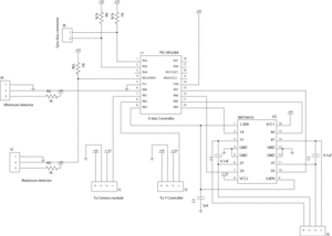
Schematic
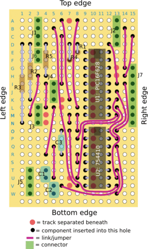
Preparing the board
Making the board
Board connections
Variations
J7 is not required if you are only driving a single motor.
Firmware
See the files section at the end for firmware for each of the three controllers. The same firmware is used for both the bipolar and unipolar motor controllers.
The network addresses for these are:
- X-Axis: 2
- Y-Axis: 3
- Z-Axis: 4
A snapshot of the latest source is available for viewing
Troubleshooting
If you experience trouble, please share the problems (and resolutions) with us.
Testing The Unit
See Also
- RepStrap
- Building A Stripboard Stepper Controller for a unipolar motor
- Building A Stripboard Comms Controller
-- Main.SimonMcAuliffe - 11 Mar 2006

